Toyota Camry (XV70): Removal
REMOVAL
CAUTION / NOTICE / HINT
The necessary procedures (adjustment, calibration, initialization or registration) that must be performed after parts are removed and installed, or replaced during fuel injector assembly removal/installation are shown below.
Necessary Procedures After Parts Removed/Installed/Replaced|
Replaced Part or Performed Procedure |
Necessary Procedure | Effect/Inoperative Function when Necessary Procedure not Performed |
Link |
|---|---|---|---|
|
*1: When performing learning using the Techstream.
Click here | |||
|
Battery terminal is disconnected/reconnected |
Perform steering sensor zero point calibration |
Lane Tracing Assist System |
|
|
Pre-collision system | |||
|
Parking Support Brake System*1 | |||
|
Memorize steering angle neutral point |
Parking assist monitor system |
| |
|
Panoramic view monitor system |
| ||
| Inspection after repair |
|
|
PROCEDURE
1. PRECAUTION
NOTICE:
After turning the engine switch off, waiting time may be required before disconnecting the cable from the negative (-) battery terminal. Therefore, make sure to read the disconnecting the cable from the negative (-) battery terminal notices before proceeding with work.
Click here .gif)
2. DISCHARGE FUEL SYSTEM PRESSURE
Click here
3. DISCONNECT CABLE FROM NEGATIVE BATTERY TERMINAL
NOTICE:
When disconnecting the cable, some systems need to be initialized after the cable is reconnected.
Click here
4. REMOVE COWL TOP VENTILATOR LOUVER SUB-ASSEMBLY
Click here
5. REMOVE FRONT CENTER UPPER SUSPENSION BRACE SUB-ASSEMBLY
Click here
6. REMOVE THROTTLE BODY WITH MOTOR ASSEMBLY
Click here
7. REMOVE V-BANK COVER SUB-ASSEMBLY
Click here
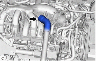
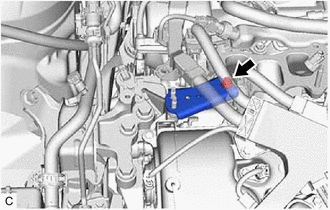
8. DISCONNECT VENTILATION HOSE
| (a) Slide the clip and disconnect the ventilation hose from the intake air surge tank assembly. |
|
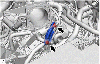
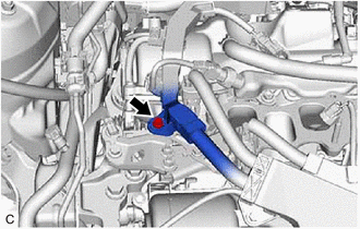
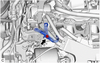
9. DISCONNECT PURGE VALVE (PURGE VSV)
| (a) Disconnect the No. 1 fuel vapor feed hose from the intake air surge tank assembly. |
|

(b) Remove the bolt and disconnect the purge valve (purge VSV) from the intake air surge tank assembly.
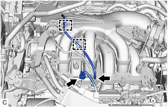
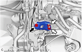
10. REMOVE NO. 2 SURGE TANK STAY
| (a) Remove the 2 bolts and No. 2 surge tank stay from the intake air surge tank assembly and camshaft housing RH. |
|
11. REMOVE INTAKE AIR SURGE TANK ASSEMBLY
| (a) Disconnect the vacuum switching valve (for ACIS) connector. |
|
(b) Disengage the 2 clamps to disconnect the vacuum hose sub-assembly from the intake air surge tank assembly.
| (c) Disengage the 2 clamps to disconnect the vacuum hose sub-assembly from the intake air surge tank assembly. |
|
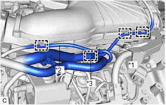
(d) Disengage the clamp to disconnect the vacuum hose from the intake air surge tank assembly.
(e) Disengage the clamp to disconnect the No. 2 air tube from the intake air surge tank assembly.
(f) Remove the 5 bolts, 2 nuts and intake air surge tank assembly from the intake manifold.
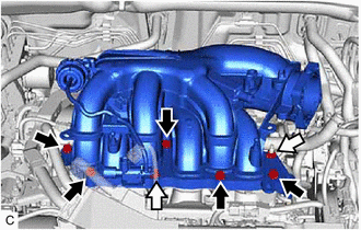
.png) |
Bolt |
.png) |
Nut |
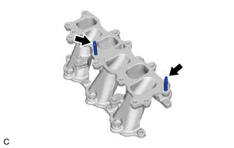
(g) Remove the plug from the intake air surge tank assembly.
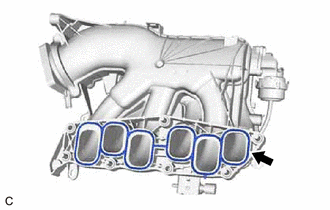
12. REMOVE AIR SURGE TANK TO INTAKE MANIFOLD GASKET
| (a) Remove the air surge tank to intake manifold gasket from the intake air surge tank assembly. |
|
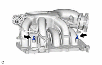
13. REMOVE NO. 1 V-BANK COVER BRACKET
HINT:
Perform this procedure only when replacement of the No. 1 V-bank cover bracket is necessary.
| (a) Remove the 2 No. 1 V-bank cover brackets from the intake air surge tank assembly. |
|
14. REMOVE NO. 2 ENGINE MOUNTING STAY RH
| (a) Remove the bolt and disconnect the wire harness clamp from the wire harness clamp bracket. |
|
| (b) Remove the bolt and separate the wire harness clamp bracket from the No. 2 engine mounting stay RH. |
|
(c) Remove the bolt, 2 nuts and No. 2 engine mounting stay RH from the engine mounting insulator sub-assembly RH.
|
|
Bolt |
|
|
Nut |
| (d) Remove the bolt and No. 2 engine mounting stay RH from the intake manifold and front No.1 engine mounting bracket LH. |
|
15. DISCONNECT FUEL TUBE SUB-ASSEMBLY
Click here
16. REMOVE FUEL DELIVERY PIPE WITH SENSOR ASSEMBLY
Click here
17. REMOVE NO. 1 DELIVERY PIPE SPACER
Click here
18. REMOVE INJECTOR VIBRATION INSULATOR
Click here
19. REMOVE INTAKE MANIFOLD
(a) Remove the 4 bolts, 4 nuts and intake manifold from the cylinder head sub-assembly.

|
|
Bolt |
|
|
Nut |
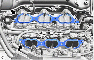
20. REMOVE NO. 1 INTAKE MANIFOLD TO HEAD GASKET
| (a) Remove the 2 No. 1 intake manifold to head gaskets from each cylinder head sub-assembly. |
|
21. REMOVE STUD BOLT
HINT:
If a stud bolt is deformed or the threads are damaged, replace it.
| (a) Using an E6 "TORX" socket wrench, remove the 2 stud bolts from the intake manifold. |
|
READ NEXT:
 Installation
INSTALLATION PROCEDURE 1. INSTALL STUD BOLT
HINT: If a stud bolt is deformed or the threads are damaged, replace it.
(a) Using an E6 "TORX" socket wrench, install the 2 stud bolts to the intak
Components
COMPONENTS ILLUSTRATION
*1 FRONT CENTER UPPER SUSPENSION BRACE SUB-ASSEMBLY
- -
Tightening torque for "Major areas involving basic vehicle performance such as moving
Removal
REMOVAL CAUTION / NOTICE / HINT
The necessary procedures (adjustment, calibration, initialization or registration) that must be performed after parts are removed and installed, or replaced during fu
SEE MORE:
Definition Of Terms
DEFINITION OF TERMS
Term Definition
Monitor description Description of what the ECM monitors and how it detects malfunctions (monitoring purpose and details).
Related DTCs Group of diagnostic trouble codes that are output by the ECM based on the same malfunction detection
System Description
SYSTEM DESCRIPTION HEATED STEERING WHEEL SYSTEM
(a) The steering heater warms up the steering wheel when the steering heater switch is turned on.
(b) The steering heater uses a control thermostat inside the steering wheel to maintain the steering wheel at the specified temperature.
OPERATIO
