Toyota Camry (XV70): Clearance Warning Buzzer
Components
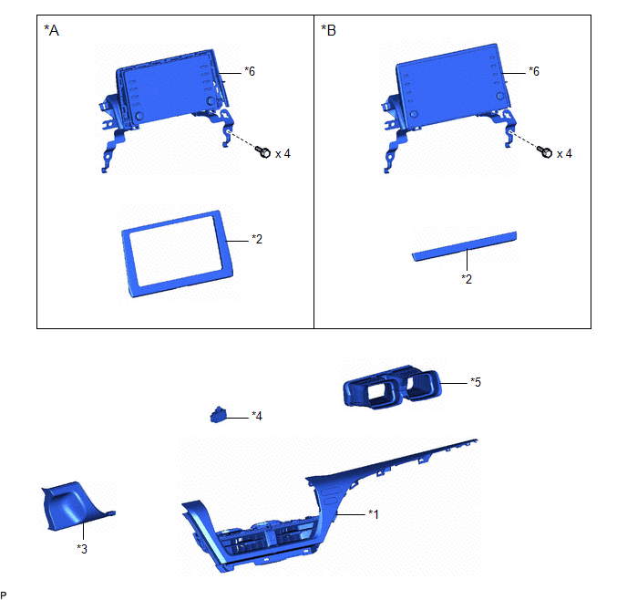
COMPONENTS
ILLUSTRATION
|
*A | for 7 Inch Display |
*B | for 9 Inch Display |
|
*1 | CENTER INSTRUMENT CLUSTER FINISH PANEL ASSEMBLY |
*2 | CENTER INSTRUMENT CLUSTER FINISH PANEL SUB-ASSEMBLY |
|
*3 | LOWER INSTRUMENT PANEL FINISH PANEL ASSEMBLY |
*4 | NO. 1 CLEARANCE WARNING BUZZER |
|
*5 | NO. 2 HEATER TO REGISTER DUCT SUB-ASSEMBLY |
*6 | RADIO AND DISPLAY RECEIVER ASSEMBLY WITH BRACKET |
Removal
REMOVAL
PROCEDURE
1. REMOVE AIR CONDITIONING CONTROL ASSEMBLY
Click here
.gif)
2. REMOVE LOWER INSTRUMENT PANEL FINISH PANEL ASSEMBLY
Click here
3. REMOVE CENTER INSTRUMENT CLUSTER FINISH PANEL SUB-ASSEMBLY (for 7 Inch Display)
Click here
4. REMOVE CENTER INSTRUMENT CLUSTER FINISH PANEL SUB-ASSEMBLY (for 9 Inch Display)
Click here
5. REMOVE CENTER INSTRUMENT CLUSTER FINISH PANEL ASSEMBLY
Click here
6. REMOVE RADIO AND DISPLAY RECEIVER ASSEMBLY WITH BRACKET (for 7 Inch Display)
Click here
7. REMOVE RADIO AND DISPLAY RECEIVER ASSEMBLY WITH BRACKET (for 9 Inch Display)
Click here
8. REMOVE NO. 2 HEATER TO REGISTER DUCT SUB-ASSEMBLY
Click here
9. REMOVE NO. 1 CLEARANCE WARNING BUZZER
| (a) Disengage the clamp. |
|

(b) Disconnect the connector to remove the No. 1 clearance warning buzzer.
Installation
INSTALLATION
PROCEDURE
1. INSTALL NO. 1 CLEARANCE WARNING BUZZER
(a) Connect the connector.
(b) Engage the clamp to install the No. 1 clearance warning buzzer.
2. INSTALL NO. 2 HEATER TO REGISTER DUCT SUB-ASSEMBLY
Click here .gif)
3. INSTALL RADIO AND DISPLAY RECEIVER ASSEMBLY WITH BRACKET (for 7 Inch Display)
Click here
4. INSTALL RADIO AND DISPLAY RECEIVER ASSEMBLY WITH BRACKET (for 9 Inch Display)
Click here
5. INSTALL CENTER INSTRUMENT CLUSTER FINISH PANEL ASSEMBLY
Click here
6. INSTALL CENTER INSTRUMENT CLUSTER FINISH PANEL SUB-ASSEMBLY (for 7 Inch Display)
Click here
7. INSTALL CENTER INSTRUMENT CLUSTER FINISH PANEL SUB-ASSEMBLY (for 9 Inch Display)
Click here
8. INSTALL LOWER INSTRUMENT PANEL FINISH PANEL ASSEMBLY
Click here
9. INSTALL AIR CONDITIONING CONTROL ASSEMBLY
Click here
READ NEXT:
 Components
COMPONENTS ILLUSTRATION
*1 CLEARANCE WARNING ECU ASSEMBLY
*2 ECU INTEGRATION BOX RH
*3 LOWER INSTRUMENT PANEL SUB-ASSEMBLY
- -
N*m (kgf*cm, ft.*lbf
Removal
REMOVAL CAUTION / NOTICE / HINT
The necessary procedures (adjustment, calibration, initialization, or registration) that must be performed after parts are removed and installed, or replaced during c
SEE MORE:
Problem Symptoms Table
PROBLEM SYMPTOMS TABLE HINT: Use the table below to help determine the cause of problem symptoms. If multiple suspected areas are listed, the potential causes of the symptoms are listed in order of probability in the "Suspected Area" column of the table. Check each symptom by checking the suspected
Initialization Switch Error (for Test Diagnosis) (C2198)
DESCRIPTION The switch circuit inside the combination meter assembly turns on and off according to the steering pad switch assembly operation.
During test mode, the tire pressure warning light blinks at 0.125 second intervals when "Set Pressure" is selected on the multi-information display, and il
