Toyota Camry (XV70): Components
COMPONENTS
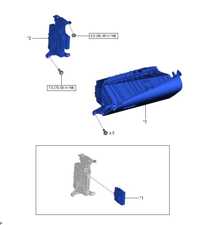
ILLUSTRATION
|
*1 | CLEARANCE WARNING ECU ASSEMBLY |
*2 | ECU INTEGRATION BOX RH |
|
*3 | LOWER INSTRUMENT PANEL SUB-ASSEMBLY |
- | - |
.png) |
N*m (kgf*cm, ft.*lbf): Specified torque |
- | - |
READ NEXT:
 Removal
REMOVAL CAUTION / NOTICE / HINT
The necessary procedures (adjustment, calibration, initialization, or registration) that must be performed after parts are removed and installed, or replaced during c
Installation
INSTALLATION PROCEDURE 1. INSTALL CLEARANCE WARNING ECU ASSEMBLY
(a) Engage the claw to install the clearance warning ECU assembly as shown in the illustration.
Install in this Dire
SEE MORE:
Fail-safe Chart
FAIL-SAFE CHART PROTECTION FUNCTION (a) The windshield wiper motor assembly operates the following protection functions if it detects an abnormal condition, in order to protect the wiper and washer system.
Item Protection Content
Conditions to Return to Normal Condition
Overh
On-vehicle Inspection
ON-VEHICLE INSPECTION PROCEDURE
1. INSPECT HOOD SUB-ASSEMBLY (a) Check that the clearance measurements of areas a through e are within each standard range.
Standard Clearance
Area Measurement
Area Measurement
a 2.8 to 6.8 mm (0.110 to 0.268 in.)
b -2 to 2
© 2023-2026 Copyright www.tocamry.com
