Toyota Camry (XV70): Components
COMPONENTS
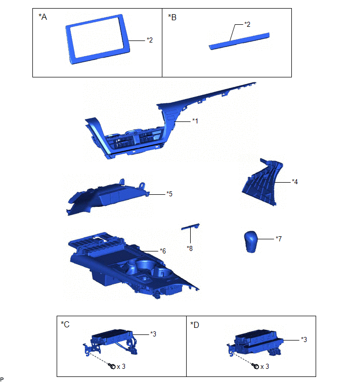
ILLUSTRATION
|
*A | for 7 Inch Display |
*B | for 9 Inch Display |
|
*C | w/o Navigation System |
*D | w/ Navigation System |
|
*1 | CENTER INSTRUMENT CLUSTER FINISH PANEL ASSEMBLY |
*2 | CENTER INSTRUMENT CLUSTER FINISH PANEL SUB-ASSEMBLY |
|
*3 | DCM (TELEMATICS TRANSCEIVER) WITH BRACKET |
*4 | INSTRUMENT PANEL FINISH PLATE GARNISH |
|
*5 | LOWER CENTER INSTRUMENT PANEL FINISH PANEL |
*6 | REAR UPPER CONSOLE PANEL SUB-ASSEMBLY |
|
*7 | SHIFT LEVER KNOB SUB-ASSEMBLY |
*8 | SHIFT LOCK RELEASE BUTTON COVER |
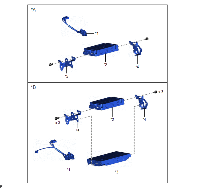
ILLUSTRATION
|
*A | w/o Navigation System |
*B | w/ Navigation System |
|
*1 | ANTENNA CORD SUB-ASSEMBLY |
*2 | DCM (TELEMATICS TRANSCEIVER) |
|
*3 | NAVIGATION ECU |
*4 | NO. 1 TELEPHONE BRACKET |
|
*5 | NO. 2 TELEPHONE BRACKET |
- | - |
READ NEXT:
 Removal
REMOVAL CAUTION / NOTICE / HINT
The necessary procedures (adjustment, calibration, initialization, or registration) that must be performed after parts are removed and installed, or replaced during D
Installation
INSTALLATION PROCEDURE 1. INSTALL DCM (TELEMATICS TRANSCEIVER)
2. INSTALL NAVIGATION ECU (w/ Navigation System) 3. INSTALL NO. 1 TELEPHONE BRACKET
(a) w/o Navigation System: (1) Install the No. 1
Manual(sos)switch
ComponentsCOMPONENTS ILLUSTRATION
*A for Normal Roof
*B except Normal Roof
*1 MANUAL (SOS) SWITCH (ROOF CONSOLE BOX ASSEMBLY)
- - RemovalREMOVAL PROCEDURE
1.
SEE MORE:
Precaution
PRECAUTION PRECAUTION FOR DISCONNECTING CABLE FROM NEGATIVE BATTERY TERMINAL
NOTICE: When disconnecting the cable from the negative (-) battery terminal, initialize the following systems after the cable is reconnected.
System Name See Procedure
Lane Tracing Assist System
Manual(sos)switch
ComponentsCOMPONENTS ILLUSTRATION
*A for Normal Roof
*B except Normal Roof
*1 MANUAL (SOS) SWITCH (ROOF CONSOLE BOX ASSEMBLY)
- - RemovalREMOVAL PROCEDURE
1. REMOVE MANUAL (SOS) SWITCH (ROOF CONSOLE BOX ASSEMBLY) Click here
InstallationINSTALLATION PRO
© 2023-2026 Copyright www.tocamry.com
