Toyota Camry (XV70): Removal
REMOVAL
CAUTION / NOTICE / HINT
The necessary procedures (adjustment, calibration, initialization, or registration) that must be performed after parts are removed and installed, or replaced during DCM (telematics transceiver) removal/installation are shown below.
Necessary Procedures After Parts Removed/Installed/Replaced|
Replaced Part or Performed Procedure |
Necessary Procedure | Effect/Inoperative Function when Necessary Procedure not Performed |
Link |
|---|---|---|---|
|
*1: w/ Smart Key System
*2: w/o Smart Key System | |||
|
DCM (telematics transceiver) |
DCM activation | Safety connect system |
|
|
Code registration | Telematics system |
| |
PROCEDURE
1. REMOVE AIR CONDITIONING CONTROL ASSEMBLY
Click here
.gif)
2. REMOVE CENTER INSTRUMENT CLUSTER FINISH PANEL SUB-ASSEMBLY (for 7 Inch Display)
Click here
3. REMOVE CENTER INSTRUMENT CLUSTER FINISH PANEL SUB-ASSEMBLY (for 9 Inch Display)
Click here
4. REMOVE CENTER INSTRUMENT CLUSTER FINISH PANEL ASSEMBLY
Click here
5. REMOVE INSTRUMENT PANEL FINISH PLATE GARNISH
Click here
6. REMOVE LOWER CENTER INSTRUMENT PANEL FINISH PANEL
Click here
7. REMOVE SHIFT LOCK RELEASE BUTTON COVER
for UB80E:
Click here
for UA80E:
Click here
for UB80F:
Click here
8. REMOVE SHIFT LEVER KNOB SUB-ASSEMBLY
for UB80E:
Click here
for UA80E:
Click here
for UB80F:
Click here
9. REMOVE REAR UPPER CONSOLE PANEL SUB-ASSEMBLY
Click here
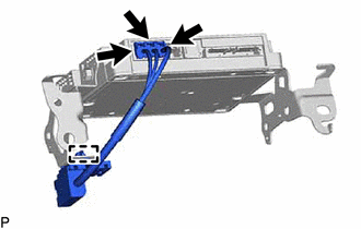
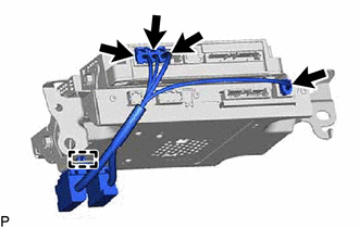
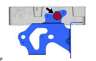
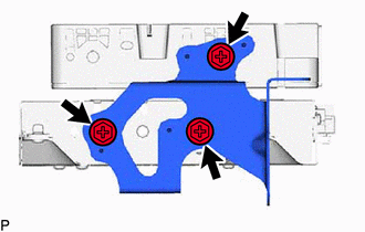
10. REMOVE DCM (TELEMATICS TRANSCEIVER) WITH BRACKET
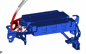
| (a) Disconnect each connector. |
|
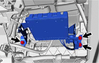
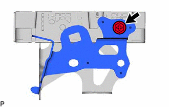
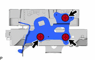
| (b) Remove the 3 bolts. |
|
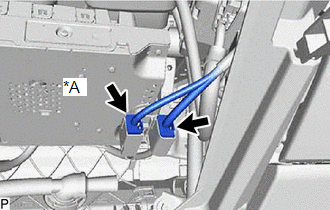
| (c) Disengage the 3 guides. |
|
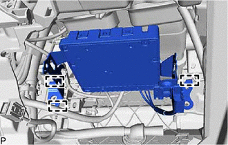
| (d) Disengage the clamp. |
|
(e) Disconnect each connector and remove the DCM (telematics transceiver) with bracket.
11. REMOVE ANTENNA CORD SUB-ASSEMBLY
(a) w/o Navigation System:
| (1) Disconnect the 3 connectors. |
|
(2) Disengage the clamp to remove the antenna cord sub-assembly.
(b) w/ Navigation System:
| (1) Disconnect the 4 connectors. |
|
(2) Disengage the clamp to remove the antenna cord sub-assembly.
12. REMOVE NO. 2 TELEPHONE BRACKET
(a) w/o Navigation System:
| (1) Remove the screw and No. 2 telephone bracket. |
|
(b) w/ Navigation System:
| (1) Remove the 3 screws and No. 2 telephone bracket. |
|
13. REMOVE NO. 1 TELEPHONE BRACKET
(a) w/o Navigation System:
| (1) Remove the screw and No. 1 telephone bracket. |
|
(b) w/ Navigation System:
| (1) Remove the 3 screws and No. 1 telephone bracket. |
|
14. REMOVE NAVIGATION ECU (w/ Navigation System)
15. REMOVE DCM (TELEMATICS TRANSCEIVER)
READ NEXT:
 Installation
INSTALLATION PROCEDURE 1. INSTALL DCM (TELEMATICS TRANSCEIVER)
2. INSTALL NAVIGATION ECU (w/ Navigation System) 3. INSTALL NO. 1 TELEPHONE BRACKET
(a) w/o Navigation System: (1) Install the No. 1
Manual(sos)switch
ComponentsCOMPONENTS ILLUSTRATION
*A for Normal Roof
*B except Normal Roof
*1 MANUAL (SOS) SWITCH (ROOF CONSOLE BOX ASSEMBLY)
- - RemovalREMOVAL PROCEDURE
1.
SEE MORE:
Components
COMPONENTS ILLUSTRATION
*A for RH Side
*B for LH Side
*1 NO. 1 FLOOR UNDER COVER
*2 NO. 2 FLOOR UNDER COVER
N*m (kgf*cm, ft.*lbf): Specified torque
- - ILLUSTRATION
*1 NO. 2 PARKING BRAKE WIRE ASSEMBLY
*2 REAR AXLE H
Components
COMPONENTS ILLUSTRATION
*A except TRD
*B for TRD
*1 LUGGAGE COMPARTMENT DOOR COVER
*2 REAR SPOILER
*3 REAR SPOILER RETAINER
- -
N*m (kgf*cm, ft.*lbf): Specified torque
● Non-reusable part
