Toyota Camry (XV70): Components
COMPONENTS
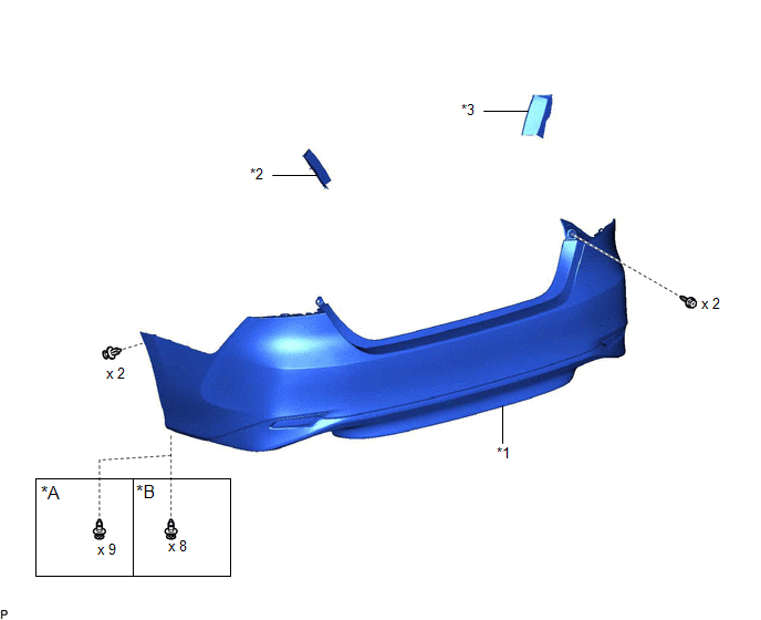
ILLUSTRATION
|
*A | for Single Type |
*B | for Dual Type |
|
*1 | REAR BUMPER ASSEMBLY |
*2 | REAR COMBINATION LIGHT COVER LH |
|
*3 | REAR COMBINATION LIGHT COVER RH |
- | - |
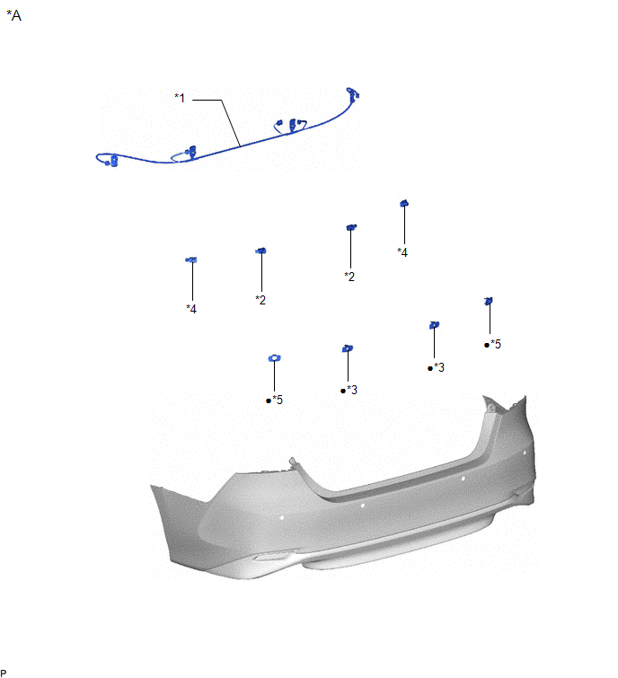
ILLUSTRATION
|
*A | w/ Parking Support Brake System |
- | - |
|
*1 | NO. 2 LUGGAGE ROOM WIRE |
*2 | REAR CENTER ULTRASONIC SENSOR |
|
*3 | REAR CENTER ULTRASONIC SENSOR RETAINER |
*4 | REAR CORNER ULTRASONIC SENSOR |
|
*5 | REAR CORNER ULTRASONIC SENSOR RETAINER |
- | - |
|
● | Non-reusable part |
- | - |
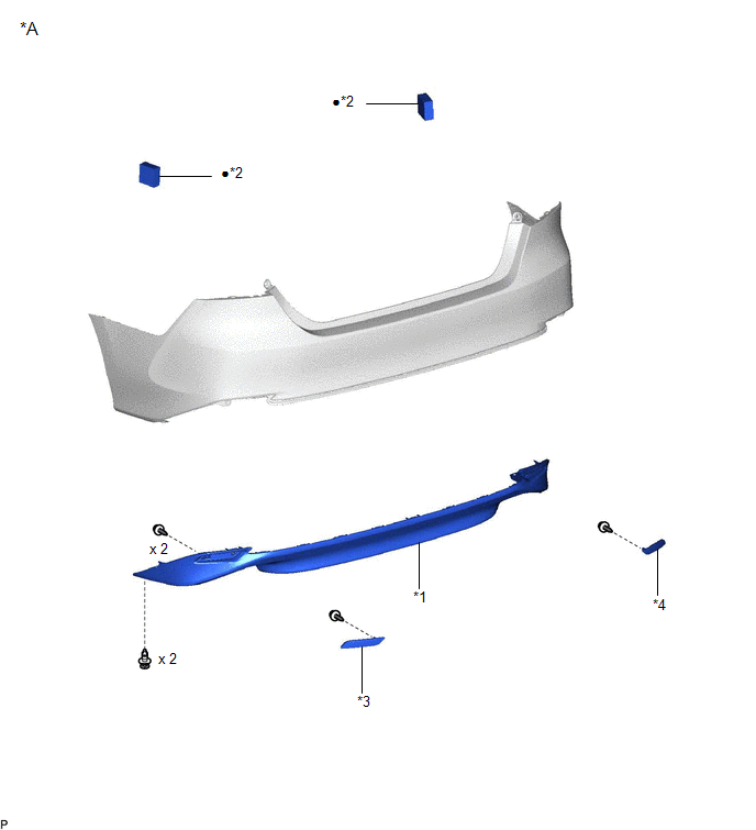
ILLUSTRATION
|
*A | for Type A |
- | - |
|
*1 | LOWER REAR BUMPER COVER |
*2 | REAR BUMPER PAD |
|
*3 | REFLEX REFLECTOR ASSEMBLY LH |
*4 | REFLEX REFLECTOR ASSEMBLY RH |
|
● | Non-reusable part |
- | - |
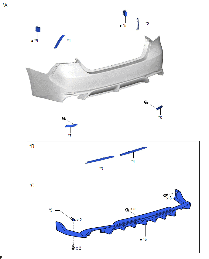
ILLUSTRATION
|
*A | for Type B |
*B | except TRD |
|
*C | for TRD |
- | - |
|
*1 | REAR BUMPER CORNER EXTENSION LH |
*2 | REAR BUMPER CORNER EXTENSION RH |
|
*3 | REAR BUMPER EXTENSION MOULDING LH |
*4 | REAR BUMPER EXTENSION MOULDING RH |
|
*5 | REAR BUMPER PAD |
*6 | REAR SPOILER |
|
*7 | REFLEX REFLECTOR ASSEMBLY LH |
*8 | REFLEX REFLECTOR ASSEMBLY RH |
|
*9 | REAR BUMPER PIECE |
- | - |
|
● | Non-reusable part |
- | - |
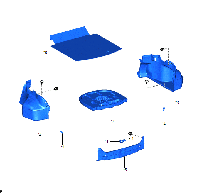
ILLUSTRATION
|
*1 | LUGGAGE COMPARTMENT DOOR STRIKER COVER |
*2 | LUGGAGE COMPARTMENT TRIM INNER COVER LH |
|
*3 | LUGGAGE COMPARTMENT TRIM INNER COVER RH |
*4 | NO. 1 LUGGAGE COMPARTMENT TRIM HOOK |
|
*5 | REAR FLOOR FINISH PLATE |
*6 | SPARE WHEEL COVER ASSEMBLY |
|
*7 | SPARE WHEEL COVER TRAY |
- | - |
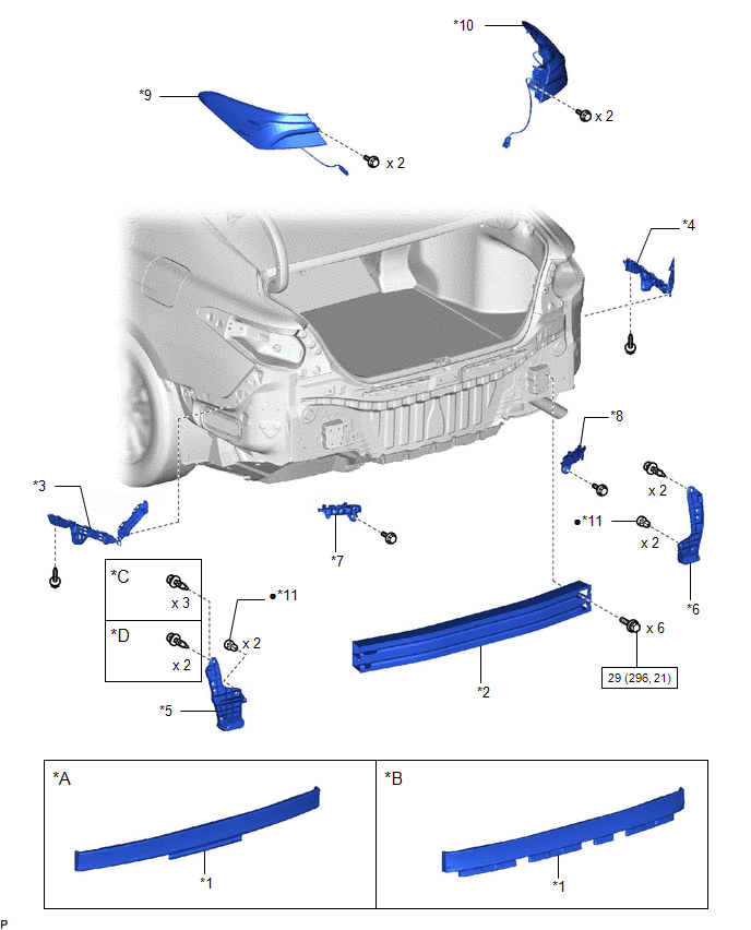
ILLUSTRATION
|
*A | for Type A |
*B | for Type B |
|
*C | for Single Type |
*D | for Dual Type |
|
*1 | REAR BUMPER ENERGY ABSORBER |
*2 | REAR BUMPER REINFORCEMENT |
|
*3 | REAR BUMPER SIDE RETAINER LH |
*4 | REAR BUMPER SIDE RETAINER RH |
|
*5 | REAR BUMPER SIDE SEAL LH |
*6 | REAR BUMPER SIDE SEAL RH |
|
*7 | REAR BUMPER UPPER RETAINER LH |
*8 | REAR BUMPER UPPER RETAINER RH |
|
*9 | REAR COMBINATION LIGHT ASSEMBLY LH |
*10 | REAR COMBINATION LIGHT ASSEMBLY RH |
|
*11 | GROMMET |
- | - |
.png) |
N*m (kgf*cm, ft.*lbf): Specified torque |
● | Non-reusable part |
READ NEXT:
 Removal
REMOVAL CAUTION / NOTICE / HINT
HINT: If the bumper is damaged, there is a possibility that the installation area of the blind spot monitor sensor may be deformed and the blind spot monitor system
Disassembly
DISASSEMBLY PROCEDURE 1. REMOVE REAR CENTER ULTRASONIC SENSOR (w/ Parking Support Brake System)
Click here HINT: Use the same procedure for the RH side and LH side.
2. REMOVE REAR CORNER ULTRA
Reassembly
REASSEMBLY PROCEDURE 1. INSTALL REAR BUMPER REINFORCEMENT
(a) Install the rear bumper reinforcement with the 6 bolts.
Torque: 29 N
SEE MORE:
Parts Location
PARTS LOCATION ILLUSTRATION
*1 BRAKE ACTUATOR ASSEMBLY
- SKID CONTROL ECU *2
ECM *3
ENGINE ROOM RELAY BLOCK AND JUNCTION BLOCK ASSEMBLY - ABS NO. 2 FUSE
- - ILLUSTRATION
*1 PARKING BRAKE ACTUATOR ASSEMBLY LH
*2 PARKING BRAKE ACTUATOR AS
Camera Heater
ComponentsCOMPONENTS ILLUSTRATION
*1 FORWARD RECOGNITION CAMERA
*2 FORWARD RECOGNITION WITH HEATER HOOD SUB-ASSEMBLY RemovalREMOVAL PROCEDURE
1. REMOVE FORWARD RECOGNITION CAMERA Click here
2. REMOVE FORWARD RECOGNITION WITH HEATER HOOD SUB-ASSEMBLY
NOTICE:
Do not
