Toyota Camry (XV70): Disassembly
DISASSEMBLY
PROCEDURE
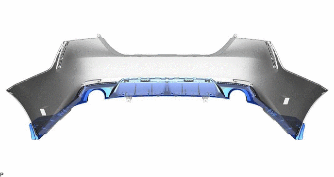
1. REMOVE REAR CENTER ULTRASONIC SENSOR (w/ Parking Support Brake System)
Click here .gif)
HINT:
Use the same procedure for the RH side and LH side.
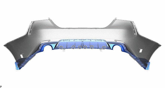
2. REMOVE REAR CORNER ULTRASONIC SENSOR (w/ Parking Support Brake System)
Click here
HINT:
Use the same procedure for the RH side and LH side.
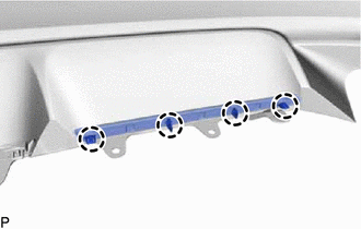
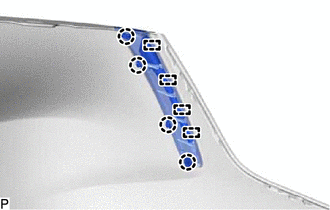
3. REMOVE REAR CENTER ULTRASONIC SENSOR RETAINER (w/ Parking Support Brake System)
Click here
HINT:
Use the same procedure for the RH side and LH side.
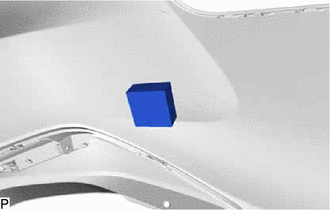
4. REMOVE REAR CORNER ULTRASONIC SENSOR RETAINER (w/ Parking Support Brake System)
Click here
HINT:
Use the same procedure for the RH side and LH side.
5. REMOVE NO. 2 LUGGAGE ROOM WIRE (w/ Parking Support Brake System)
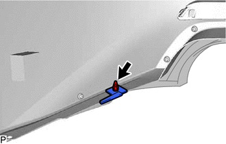
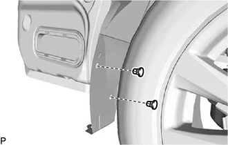
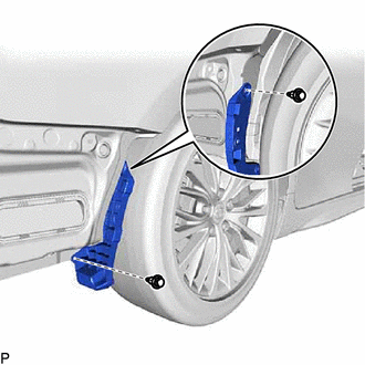
6. REMOVE REFLEX REFLECTOR ASSEMBLY LH
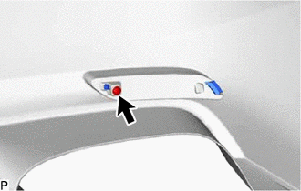
(a) Remove the screw.
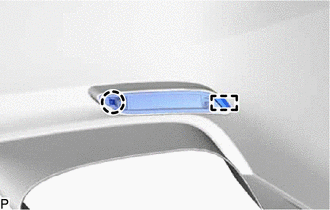
| (b) Disengage the claw and guide to remove the reflex reflector assembly LH. |
|
7. REMOVE REFLEX REFLECTOR ASSEMBLY RH
HINT:
Use the same procedure as for the LH side.
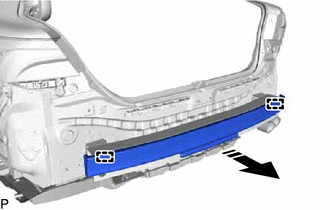
8. REMOVE LOWER REAR BUMPER COVER (for Type A)
(a) Remove the 2 screws.
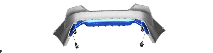
(b) Remove the 2 clips.
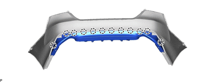
(c) Disengage the 12 claws to remove the lower rear bumper cover.
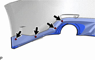
9. REMOVE REAR BUMPER EXTENSION MOULDING LH (for Type B)
(a) except TRD:
| (1) Disengage the 4 claws to remove the rear bumper extension moulding LH. |
|
10. REMOVE REAR BUMPER EXTENSION MOULDING RH (for Type B)
except TRD:
HINT:
Use the same procedure as for the LH side.
11. REMOVE REAR SPOILER (for Type B)
(a) for TRD:
| (1) Remove the clip and rear bumper piece. HINT: Use the same procedure for the RH side and LH side. |
|
| (2) Remove the 4 screws. HINT: Use the same procedure for the RH side and LH side. |
|
| (3) Remove the 5 screws. |
|
(4) Separate the double-sided tape.
.png) |
Double-sided Tape | - |
- |
(5) Disengage the 6 claws to remove the rear spoiler.
12. REMOVE REAR BUMPER CORNER EXTENSION LH (for Type B)
| (a) Disengage the 4 claws and 4 guides to remove the rear bumper corner extension LH. |
|
13. REMOVE REAR BUMPER CORNER EXTENSION RH (for Type B)
HINT:
Use the same procedure as for the LH side.
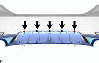
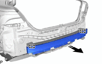
14. REMOVE REAR BUMPER PAD
| (a) Remove the rear bumper pad. HINT: Use the same procedure for the RH side and LH side. |
|
15. REMOVE SPARE WHEEL COVER ASSEMBLY
Click here
16. REMOVE SPARE WHEEL COVER TRAY
Click here
17. REMOVE NO. 1 LUGGAGE COMPARTMENT TRIM HOOK
Click here
18. REMOVE LUGGAGE COMPARTMENT DOOR STRIKER COVER
Click here
19. REMOVE REAR FLOOR FINISH PLATE
Click here
20. REMOVE LUGGAGE COMPARTMENT TRIM INNER COVER RH
Click here
21. REMOVE LUGGAGE COMPARTMENT TRIM INNER COVER LH
Click here
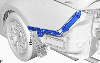
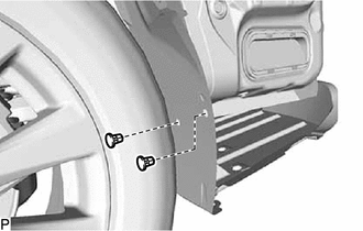
22. REMOVE REAR BUMPER SIDE RETAINER LH
| (a) Remove the screw. |
|
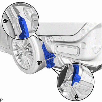
(b) Disengage the 3 clips as shown in the illustration.
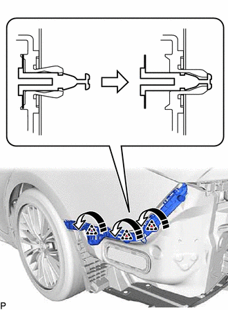
.png) |
Remove in this Direction |
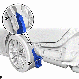
(c) Disengage the 2 claws as shown in the illustration.
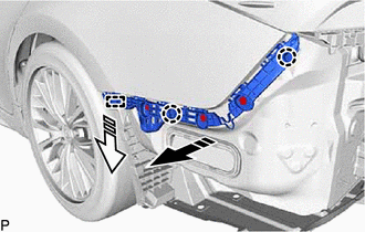
|
|
Remove in this Direction (1) |
.png) |
Remove in this Direction (2) |
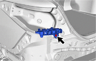
(d) Disengage the guide to remove the rear bumper side retainer LH.
23. REMOVE REAR BUMPER SIDE RETAINER RH
HINT:
Use the same procedure as for the LH side.
24. REMOVE REAR COMBINATION LIGHT ASSEMBLY LH
Click here
25. REMOVE REAR COMBINATION LIGHT ASSEMBLY RH
HINT:
Use the same procedure as for the LH side.
26. REMOVE REAR BUMPER UPPER RETAINER LH
| (a) Remove the screw and rear bumper upper retainer LH. |
|
27. REMOVE REAR BUMPER UPPER RETAINER RH
HINT:
Use the same procedure as for the LH side.
28. REMOVE REAR BUMPER SIDE SEAL LH
| (a) Remove the 2 grommets. |
|
| (b) for Single Type: (1) Remove the 3 clips and rear bumper side seal LH. |
|
| (c) for Dual Type: (1) Remove the 2 clips and rear bumper side seal LH. |
|
29. REMOVE REAR BUMPER SIDE SEAL RH
| (a) Remove the 2 grommets. |
|
| (b) Remove the 2 clips and rear bumper side seal RH. |
|
30. REMOVE REAR BUMPER ENERGY ABSORBER (for Type A)
(a) Disengage the 2 guides to remove the rear bumper energy absorber as shown in the illustration.
|
|
Remove in this Direction |
31. REMOVE REAR BUMPER ENERGY ABSORBER (for Type B)
(a) Disengage the 2 guides to remove the rear bumper energy absorber as shown in the illustration.
|
|
Remove in this Direction |
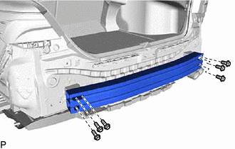
32. REMOVE REAR BUMPER REINFORCEMENT
| (a) Remove the 6 bolts and rear bumper reinforcement. |
|
READ NEXT:
 Reassembly
REASSEMBLY PROCEDURE 1. INSTALL REAR BUMPER REINFORCEMENT
(a) Install the rear bumper reinforcement with the 6 bolts.
Torque: 29 N
Installation
INSTALLATION CAUTION / NOTICE / HINT
HINT: When the rear bumper is damaged or deformed due to an accident or contact with other objects, etc., or the bumper installation area on the body is repaire
SEE MORE:
Checking Monitor Status
CHECKING MONITOR STATUS The purpose of the monitor result (mode 06) is to allow access to the results of on-board diagnostic monitoring tests of specific components/systems that are not continuously monitored. Examples are catalysts and evaporative emissions (EVAP) systems.
The monitor result allo
Components
COMPONENTS ILLUSTRATION
*1 NO. 1 ENGINE UNDER COVER
*2 NO. 2 ENGINE UNDER COVER ASSEMBLY
*3 FRONT WHEEL OPENING EXTENSION PAD LH
*4 FRONT WHEEL OPENING EXTENSION PAD RH
*5 FRONT FENDER APRON SEAL LH
- -
N*m (kgf*cm, ft.*lbf): Spe
