Toyota Camry (XV70): Removal
REMOVAL
CAUTION / NOTICE / HINT
HINT:
If the bumper is damaged, there is a possibility that the installation area of the blind spot monitor sensor may be deformed and the blind spot monitor system may not operate correctly, so visually inspect the blind spot monitor sensor installation area (frame, stud bolt) to make sure it is not dented or bent.
Click here .gif)
If the visual inspection finds a problem, check the installation condition of the blind spot monitor sensor, and adjust the installation position of the blind spot monitor sensor as necessary.
PROCEDURE
1. REMOVE REAR COMBINATION LIGHT COVER LH
Click here
2. REMOVE REAR COMBINATION LIGHT COVER RH
HINT:
Use the same procedure as for the LH side.
3. REMOVE REAR BUMPER ASSEMBLY
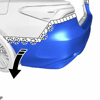
(a) Apply protective tape around the rear bumper assembly as shown in the illustration.
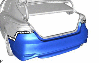
.png) |
Protective Tape |
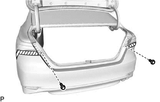
| (b) Remove the 2 screws. |
|
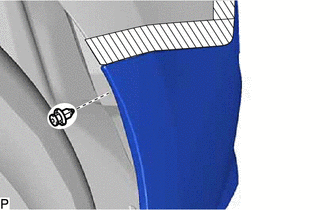
| (c) Remove the clip. HINT: Use the same procedure for the RH side and LH side. |
|
| (d) for Single Type: (1) Remove the 9 clips. |
|
| (e) for Dual Type: (1) Remove the 8 clips. |
|
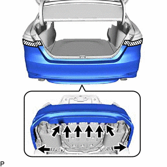
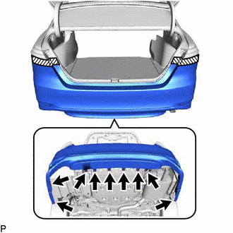
(f) Disengage the 6 claws as shown in the illustration.
.png) |
Remove in this Direction |
HINT:
Use the same procedure for the RH side and LH side.
(g) Disengage the 4 claws and 2 guides to remove the rear bumper assembly as shown in the illustration.
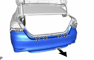
|
|
Remove in this Direction |
(h) w/ Intuitive Parking Assist System:
(1) Disconnect the connector to remove the rear bumper assembly.
READ NEXT:
 Disassembly
DISASSEMBLY PROCEDURE 1. REMOVE REAR CENTER ULTRASONIC SENSOR (w/ Parking Support Brake System)
Click here HINT: Use the same procedure for the RH side and LH side.
2. REMOVE REAR CORNER ULTRA
Reassembly
REASSEMBLY PROCEDURE 1. INSTALL REAR BUMPER REINFORCEMENT
(a) Install the rear bumper reinforcement with the 6 bolts.
Torque: 29 N
Installation
INSTALLATION CAUTION / NOTICE / HINT
HINT: When the rear bumper is damaged or deformed due to an accident or contact with other objects, etc., or the bumper installation area on the body is repaire
SEE MORE:
Headlight switch
Operating instructions
Operating the switch turns on
the lights as follows:
For U.S.A.
The headlights, daytime
running lights and all the lights
listed below turn on and
off automatically.
(Vehicles without a
smart key system:
When the engine
switch is in the "ON"
position)
Disassembly
DISASSEMBLY CAUTION / NOTICE / HINT
The necessary procedures (adjustment, calibration, initialization, or registration) that must be performed after parts are removed and installed, or replaced during rear door removal/installation are shown below. Necessary Procedure After Parts Removed/Installe
