Toyota Camry (XV70): Components
COMPONENTS
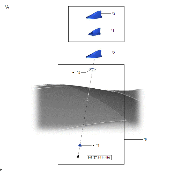
ILLUSTRATION
|
*A | except Panoramic Moon Roof |
- | - |
|
*1 | TELEPHONE AND GPS ANTENNA ASSEMBLY |
*2 | TELEPHONE AND GPS ANTENNA ASSEMBLY WITH COVER |
|
*3 | COVER |
*4 | WASHER AND HOLDER |
|
*5 | SEAL |
*6 | TELEPHONE ANTENNA HOUSING |
.png) |
N*m (kgf*cm, ft.*lbf): Specified torque |
● | Non-reusable part |
ILLUSTRATION
.png)
|
*A | for Panoramic Moon Roof |
- | - |
|
*1 | TELEPHONE AND GPS ANTENNA ASSEMBLY |
- | - |
|
|
N*m (kgf*cm, ft.*lbf): Specified torque |
- | - |
READ NEXT:
 Removal
REMOVAL CAUTION / NOTICE / HINT
The necessary procedures (adjustment, calibration, initialization, or registration) that must be performed after parts are removed and installed, or replaced during t
Installation
INSTALLATION PROCEDURE 1. INSTALL TELEPHONE AND GPS ANTENNA ASSEMBLY (except Panoramic Moon Roof)
(a) When reusing the telephone and GPS antenna assembly: (1) Install a new seal.
(b) Push the tele
Telephone And Gps Antenna Cords (for Front Side)
ComponentsCOMPONENTS ILLUSTRATION
*1 INSTRUMENT PANEL SAFETY PAD SUB-ASSEMBLY
*2 NO. 2 SIDE DEFROSTER NOZZLE DUCT
*3 NO. 3 HEATER TO REGISTER DUCT SUB-ASSEMBLY
*4
SEE MORE:
Moon roof
Use the overhead switches to open and close the moon roof and
tilt it up and down.
Opening and closing
Opens the moon roof*
The moon roof stops slightly before
the fully open position to reduce
wind noise.
Press the switch again to fully open
the moon roof.
Closes the moon roof*
Removal
REMOVAL CAUTION / NOTICE / HINT
The necessary procedures (adjustment, calibration, initialization or registration) that must be performed after parts are removed and installed, or replaced generator assembly removal/installation are shown below. Necessary Procedures After Parts Removed/Installed/R
© 2023-2026 Copyright www.tocamry.com
