Toyota Camry (XV70): Components
COMPONENTS
ILLUSTRATION
|
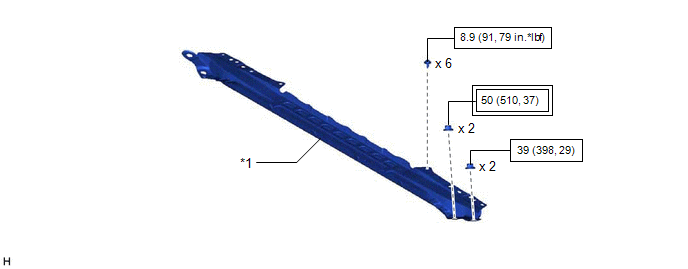
*1 | FRONT CENTER UPPER SUSPENSION BRACE SUB-ASSEMBLY |
- | - |
.png) |
Tightening torque for "Major areas involving basic vehicle performance such as moving/turning/stopping": N*m (kgf*cm, ft.*lbf) |
 |
N*m (kgf*cm, ft.*lbf): Specified torque |
ILLUSTRATION
|
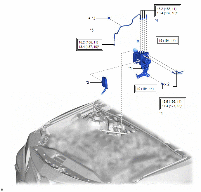
*1 | BRAKE ACTUATOR WITH BRACKET |
*2 | CONNECTOR |
|
*3 | BRAKE TUBE CLAMP |
*4 | BRAKE LINE |
|
*5 | FRONT NO. 3 BRAKE TUBE |
- | - |
|
|
Tightening torque for "Major areas involving basic vehicle performance such as moving/turning/stopping": N*m (kgf*cm, ft.*lbf) |
* | For use with a union nut wrench |
|
● | Non-reusable part |
- | - |
ILLUSTRATION
|
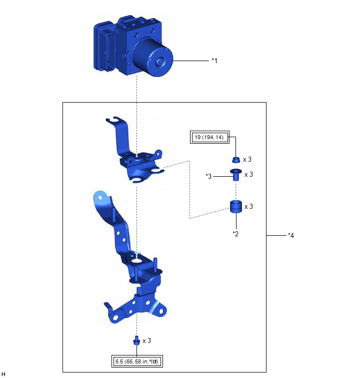
*1 | BRAKE ACTUATOR ASSEMBLY |
*2 | BRAKE ACTUATOR BRACKET CUSHION |
|
*3 | NO. 2 BRAKE ACTUATOR CASE COLLAR |
*4 | BRAKE ACTUATOR BRACKET ASSEMBLY |
|
|
Tightening torque for "Major areas involving basic vehicle performance such as moving/turning/stopping": N*m (kgf*cm, ft.*lbf) |
- | - |
READ NEXT:
 On-vehicle Inspection
ON-VEHICLE INSPECTION PROCEDURE
1. CONNECT TECHSTREAM (a) Connect the Techstream to the DLC3 with the ignition switch off.
(b) Start the engine and run it at idle. (c) Turn the Techstream on.
(d
Removal
REMOVAL CAUTION / NOTICE / HINT
The necessary procedures (adjustment, calibration, initialization or registration) that must be performed after parts are removed and installed, or replaced during br
Installation
INSTALLATION CAUTION / NOTICE / HINT w/ Electric Parking Brake System:
HINT: The parking brake indicator light blinks (red) when the engine switch is turned on after replacing the brake actuator ass
SEE MORE:
Removal
REMOVAL CAUTION / NOTICE / HINT
The necessary procedures (adjustment, calibration, initialization or registration) that must be performed after parts are removed and installed, or replaced during canister (charcoal canister assembly) removal/installation are shown below. Necessary Procedures After
Parking Brake Switch Circuit
DESCRIPTION This circuit is from the skid control ECU (brake actuator assembly) to the radio and display receiver assembly. WIRING DIAGRAM
PROCEDURE
1.
CHECK BRAKE WARNING LIGHT (a) Check that the brake warning light comes on when the parking brake is applied and goes off when it is
