Toyota Camry (XV70): Transmitter Battery(w/o Smart Key System)
Components
COMPONENTS
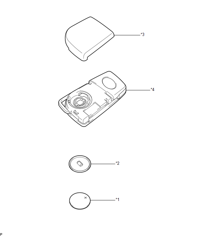
ILLUSTRATION
|
*1 | TRANSMITTER BATTERY |
*2 | TRANSMITTER BATTERY HOUSING COVER |
|
*3 | TRANSMITTER HOUSING COVER |
*4 | TRANSMITTER HOUSING CASE |
Removal
REMOVAL
PROCEDURE
1. REMOVE TRANSMITTER BATTERY
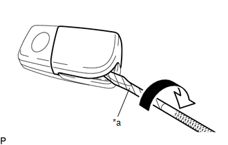
| (a) Insert a screwdriver into the gap, and turn the screwdriver to remove the transmitter housing cover. HINT: Tape the screwdriver tip before use. |
|
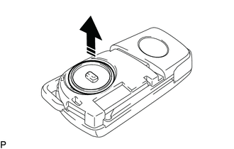
(b) Remove the transmitter battery housing cover as shown in the illustration.
.png) |
Remove in this Direction |
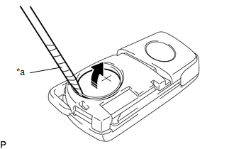
(c) Insert a precision screwdriver into the gap and gently remove the transmitter battery (lithium battery: CR2032) as shown in the illustration.
NOTICE:
- Do not push the terminals with your finger.
- Do not forcibly pry up the transmitter battery as the terminals may be damaged.
- Do not touch the transmitter battery with wet hands. Moisture may cause rust.
- Do not touch or move any components inside the transmitter housing case. It may interfere with proper operation.
- When replacing the transmitter battery, before starting work, remove static electricity that has built up in the body by touching, for example, the vehicle to prevent the electrical key transmitter sub-assembly from being damaged.
HINT:
Tape the screwdriver tip before use.
|
*a | Protective Tape |
|
|
Remove in this Direction |
Installation
INSTALLATION
PROCEDURE
1. INSTALL TRANSMITTER BATTERY
(a) Install the transmitter battery (lithium battery: CR2032) with the positive (+) side facing upward, as shown in the illustration.
NOTICE:
- Do not bend the transmitter battery electrode during installation.
- Keep the inside of the transmitter housing cover free of dust and oil.
- When replacing the transmitter battery, before starting work, remove static electricity that has built up in the body by touching, for example, the vehicle to prevent the electrical key transmitter sub-assembly from being damaged.
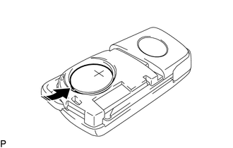
.png) |
Install in this Direction |
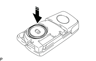
(b) Install the transmitter battery housing cover as shown in the illustration.
|
|
Install in this Direction |
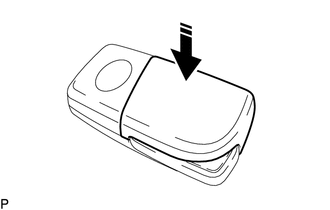
(c) Install the transmitter housing cover by pressing down on it as shown in the illustration.
|
|
Install in this Direction |
READ NEXT:
 Components
COMPONENTS ILLUSTRATION
*1 REAR ENGINE UNDER COVER LH
*2 FRONT FENDER APRON SEAL LH
*3 NO. 1 ENGINE UNDER COVER
*4 FRONT WHEEL OPENING EXTENSION PAD LH
*5
Replacement
REPLACEMENT CAUTION / NOTICE / HINT
The necessary procedures (adjustment, calibration, initialization, or registration) that must be performed after parts are removed and installed, or replaced duri
SEE MORE:
Removal
REMOVAL CAUTION / NOTICE / HINT
The necessary procedures (adjustment, calibration, initialization, or registration) that must be performed after parts are removed and installed, or replaced during steering wheel assembly removal/installation are shown below. Necessary Procedures After Parts Remov
Components
COMPONENTS ILLUSTRATION
*A for 2WD
- -
*1 REAR SUSPENSION MEMBER SUB-ASSEMBLY
*2 REAR UPPER CONTROL ARM ASSEMBLY LH
*3 REAR UPPER CONTROL ARM ASSEMBLY RH
- -
Tightening torque for "Major areas involving basic vehicle performance
