Toyota Camry (XV70): Components
COMPONENTS
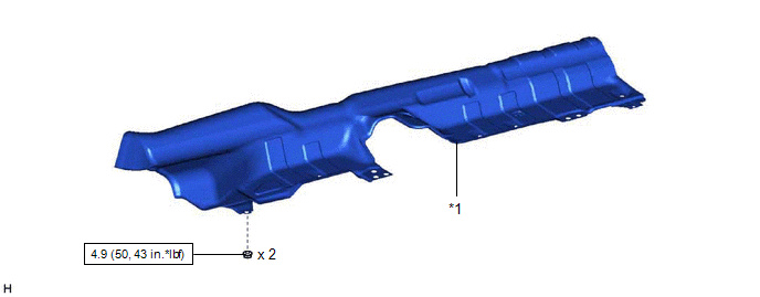
ILLUSTRATION
|
*1 | FRONT LOWER NO. 1 FLOOR HEAT INSULATOR |
- | - |
.png) |
N*m (kgf*cm, ft.*lbf): Specified torque |
- | - |
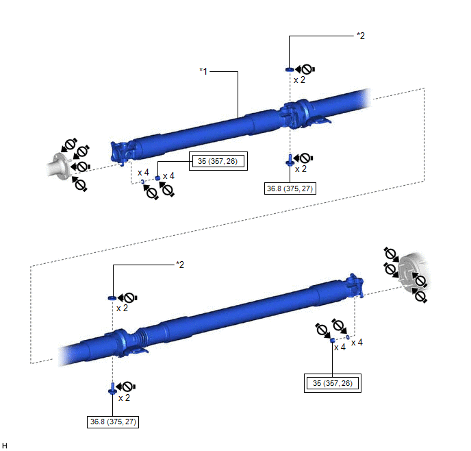
ILLUSTRATION
|
*1 | PROPELLER WITH CENTER BEARING SHAFT ASSEMBLY |
*2 | CENTER NO. 2 SUPPORT BEARING WASHER |
.png) |
Tightening torque for "Major areas involving basic vehicle performance such as moving/turning/stopping": N*m (kgf*cm, ft.*lbf) |
|
N*m (kgf*cm, ft.*lbf): Specified torque |
.png) |
Do not apply lubricants |
- | - |
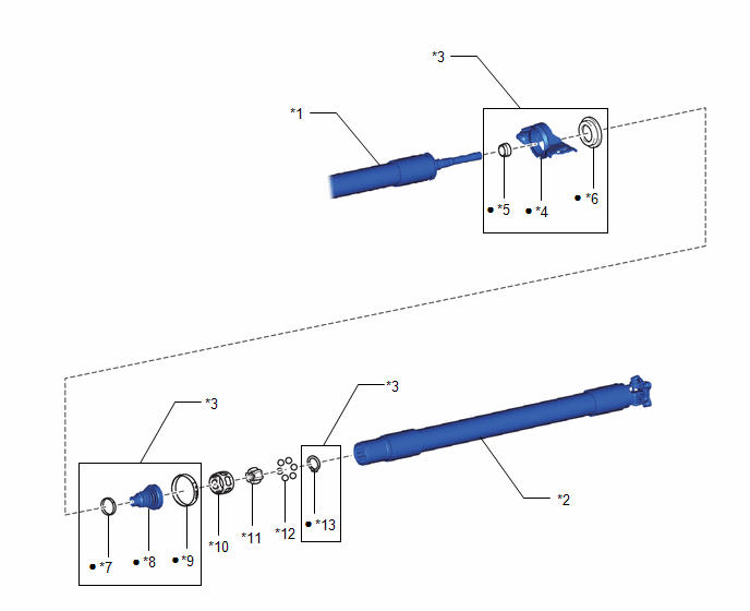
ILLUSTRATION
|
*1 | PROPELLER INTERMEDIATE SHAFT ASSEMBLY |
*2 | REAR PROPELLER SHAFT ASSEMBLY |
|
*3 | UNIVERSAL BOOT KIT |
*4 | CENTER SUPPORT BEARING |
|
*5 | NO. 1 DUST DEFLECTOR |
*6 | FLANGE |
|
*7 | SMALL DIAMETER PROPELLER SHAFT BOOT CLAMP |
*8 | PROPELLER SHAFT BOOT |
|
*9 | LARGE DIAMETER PROPELLER SHAFT BOOT CLAMP |
*10 | BALL CAGE |
|
*11 | INNER RACE |
*12 | BALL |
|
*13 | PROPELLER SHAFT SNAP RING |
- | - |
|
● | Non-reusable part |
- | - |
READ NEXT:
 Removal
REMOVAL CAUTION / NOTICE / HINT
The necessary procedures (adjustment, calibration, initialization, or registration) that must be performed after parts are removed and installed, or replaced during p
Disassembly
DISASSEMBLY CAUTION / NOTICE / HINT
NOTICE:
As imbalance affects vibration and noise performance, make sure to ensure correct angular alignment of the following components during installation.
Inspection
INSPECTION PROCEDURE 1. INSPECT PROPELLER WITH CENTER BEARING SHAFT ASSEMBLY
(a) Using a dial indicator, measure the runout of the rear propeller shaft assembly (for front side).
Maximum Runo
SEE MORE:
Installation
INSTALLATION PROCEDURE 1. INSTALL ROOF ANTENNA ASSEMBLY (except Panoramic Moon Roof)
(a) When reusing the roof antenna assembly: (1) Install a new seal.
(b) Push the roof antenna assembly in the direction indicated by the arrow (1) shown in the illustration to engage the guide.
On-vehicle Inspection
ON-VEHICLE INSPECTION CAUTION / NOTICE / HINT
CAUTION: Do not remove the radiator cap sub-assembly while the engine and radiator assembly are still hot. Pressurized, hot engine coolant and steam may be released and cause serious burns.
PROCEDURE
1. CHECK RADIATOR CAP SUB-ASSEMBLY CAUTION: Do
© 2023-2026 Copyright www.tocamry.com
