Toyota Camry (XV70): Inspection
INSPECTION
PROCEDURE
1. INSPECT PROPELLER WITH CENTER BEARING SHAFT ASSEMBLY
| (a) Using a dial indicator, measure the runout of the rear propeller shaft assembly (for front side). Maximum Runout: 0.6 mm (0.0236 in.) NOTICE: The dial indicator must be set at a right angle to the center of the rear propeller shaft assembly. If the shaft runout exceeds the maximum, replace the propeller with center bearing shaft assembly. |
|
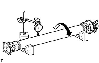
| (b) Using a dial indicator, measure the runout of the rear propeller shaft assembly (for rear side). Maximum Runout: 0.6 mm (0.0236 in.) NOTICE: The dial indicator must be set at a right angle to the center of the rear propeller shaft assembly. If the shaft runout exceeds the maximum, replace the propeller with center bearing shaft assembly. |
|
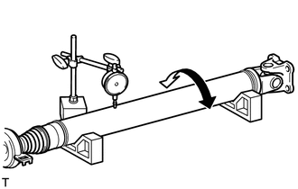
| (c) Using a dial indicator, measure the runout of the intermediate shaft assembly. Maximum Runout: 0.6 mm (0.0236 in.) NOTICE: The dial indicator must be set at a right angle to the center of the intermediate shaft assembly. If the shaft runout exceeds the maximum, replace the propeller with center bearing shaft assembly. |
|
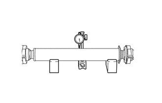
(d) Check that there is no excessive play and the joint part moves smoothly when moving the joint part up and down, left and right, and in the direction of the axis.
READ NEXT:
 Reassembly
REASSEMBLY CAUTION / NOTICE / HINT
NOTICE:
As imbalance affects vibration and noise performance, make sure to ensure correct angular alignment of the following components during installation.
Installation
INSTALLATION PROCEDURE 1. TEMPORARILY TIGHTEN PROPELLER WITH CENTER BEARING SHAFT ASSEMBLY
(a) When reusing a propeller with center bearing shaft assembly and rear differential carrier assembly:
Propeller Shaft System
Problem Symptoms TablePROBLEM SYMPTOMS TABLE
HINT: Use the table below to help determine the cause of problem symptoms. If multiple suspected areas are listed, the potential causes of the symptoms a
SEE MORE:
Sound of Portable Player cannot be Heard from Speakers or Sound is Low
PROCEDURE
1. CHECK PORTABLE PLAYER SETTINGS
(a) Check the portable player settings. (1) Check that the volume is not set to "0".
(2) Check that mute is off. (b) Check that the sound of the portable player can be heard from the speakers.
OK: Sound of the portable player can be hear
Data List / Active Test
DATA LIST / ACTIVE TEST DATA LIST HINT:
Using the Techstream to read the Data List allows the values or states of switches, sensors, actuators and other items to be read without removing any parts. This non-intrusive inspection can be very useful because intermittent conditions or signals may be
