
Toyota Camry (XV70): Removal
REMOVAL
CAUTION / NOTICE / HINT
The necessary procedures (adjustment, calibration, initialization, or registration) that must be performed after parts are removed and installed, or replaced during propeller with center bearing shaft assembly removal/installation are shown below.
Necessary Procedures After Parts Removed/Installed/Replaced|
Replaced Part or Performed Procedure |
Necessary Procedure | Effect/Inoperative Function when Necessary Procedure not Performed |
Link |
|---|---|---|---|
| Exhaust system parts |
Inspection after repair |
|
|
CAUTION:
To prevent burns, do not touch the engine, exhaust pipe or other high temperature components while the engine is hot.
.png)
PROCEDURE
1. REMOVE EXHAUST PIPE ASSEMBLY
Click here
.gif)
2. REMOVE FRONT LOWER NO. 1 FLOOR HEAT INSULATOR
Click here
3. REMOVE PROPELLER WITH CENTER BEARING SHAFT ASSEMBLY
| (a) Put matchmarks on the rear differential carrier assembly and propeller with center bearing shaft assembly. |
|
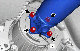
(b) Remove the 4 nuts and 4 washers.
(c) Using a brass bar and a hammer, separate the propeller with center bearing shaft assembly.
NOTICE:
Use wire or an equivalent tool to keep the propeller with center bearing shaft assembly.
| (d) Remove the 2 bolts and 2 center No. 2 support bearing washers (for rear side). NOTICE: When removing the bolts and center No. 2 support bearing washers, do not apply excessive force to the universal joint. |
|
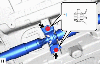
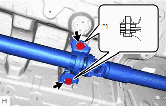
| (e) Remove the 2 bolts and 2 center No. 2 support bearing washers (for front side). NOTICE: When removing the bolts and center No. 2 support bearing washers, do not apply excessive force to the universal joint. |
|
| (f) Put matchmarks on the transfer assembly and propeller with center bearing shaft assembly. |
|
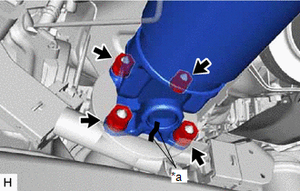
(g) Remove the 4 nuts, 4 washers and propeller with center bearing shaft assembly from the transfer assembly.
NOTICE:
- When removing the propeller with center bearing shaft assembly, do not apply excessive force to the universal joint.
- During and after the removal of the propeller with center bearing shaft assembly, keep the universal joint angle straight (within 15 degrees).
READ NEXT:
 Disassembly
DISASSEMBLY CAUTION / NOTICE / HINT
NOTICE:
As imbalance affects vibration and noise performance, make sure to ensure correct angular alignment of the following components during installation.
Inspection
INSPECTION PROCEDURE 1. INSPECT PROPELLER WITH CENTER BEARING SHAFT ASSEMBLY
(a) Using a dial indicator, measure the runout of the rear propeller shaft assembly (for front side).
Maximum Runo
Reassembly
REASSEMBLY CAUTION / NOTICE / HINT
NOTICE:
As imbalance affects vibration and noise performance, make sure to ensure correct angular alignment of the following components during installation.
SEE MORE:
Yaw Rate Sensor Circuit Intermittent (C00631F,C006396,C05201F)
DESCRIPTION The airbag sensor assembly has a built-in yaw rate and acceleration sensor and detects the vehicle condition.
These DTCs are stored when the skid control ECU (brake actuator assembly) receives a malfunction signal from the yaw rate and acceleration sensor (airbag sensor assembly).
Weak Blower Output
DESCRIPTION If the airflow from the front registers is weak regardless of the blower speed setting displayed on the air conditioning control assembly, the following suspected areas may be the cause.
Symptom Factor
Airflow volume is constantly low
Airflow volume sometimes become
