Toyota Camry (XV70): Components
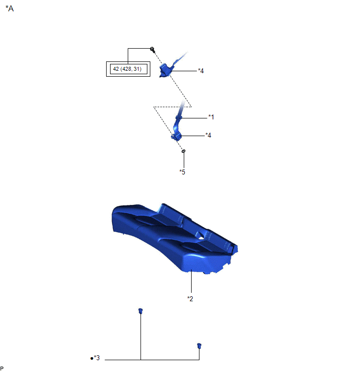
COMPONENTS
ILLUSTRATION
|
*A | for Fold Down Seat Type |
- | - |
|
*1 | REAR CENTER SEAT OUTER BELT ASSEMBLY |
*2 | REAR SEAT CUSHION ASSEMBLY |
|
*3 | REAR SEAT CUSHION LOCK HOOK |
*4 | REAR SEAT INNER BELT ASSEMBLY RH |
|
*5 | WASHER |
- | - |
.png) |
Tightening torque for "Major areas involving basic vehicle performance such as moving/turning/stopping": N*m (kgf*cm, ft.*lbf) |
● | Non-reusable part |
ILLUSTRATION
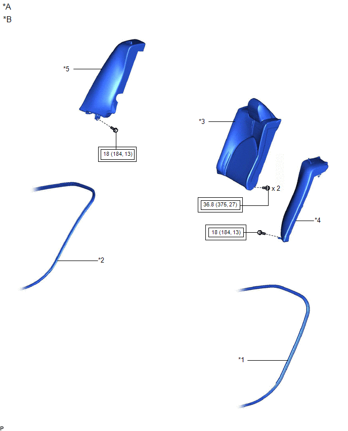
|
*A | for Fold Down Seat Type |
*B | w/o Removable Headrest |
|
*1 | REAR DOOR OPENING TRIM WEATHERSTRIP LH |
*2 | REAR DOOR OPENING TRIM WEATHERSTRIP RH |
|
*3 | REAR SEATBACK ASSEMBLY LH |
*4 | REAR SIDE SEATBACK ASSEMBLY LH |
|
*5 | REAR SIDE SEATBACK ASSEMBLY RH |
- | - |
|
|
Tightening torque for "Major areas involving basic vehicle performance such as moving/turning/stopping": N*m (kgf*cm, ft.*lbf) |
- | - |
ILLUSTRATION
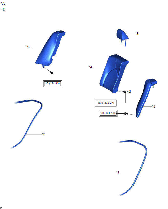
|
*A | for Fold Down Seat Type |
*B | w/ Removable Headrest |
|
*1 | REAR DOOR OPENING TRIM WEATHERSTRIP LH |
*2 | REAR DOOR OPENING TRIM WEATHERSTRIP RH |
|
*3 | REAR SEAT HEADREST ASSEMBLY LH |
*4 | REAR SEATBACK ASSEMBLY LH |
|
*5 | REAR SIDE SEATBACK ASSEMBLY LH |
*6 | REAR SIDE SEATBACK ASSEMBLY RH |
|
|
Tightening torque for "Major areas involving basic vehicle performance such as moving/turning/stopping": N*m (kgf*cm, ft.*lbf) |
- | - |
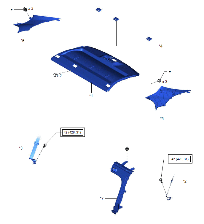
ILLUSTRATION
|
*1 | PACKAGE TRAY TRIM PANEL ASSEMBLY |
*2 | REAR SEAT OUTER BELT ASSEMBLY LH |
|
*3 | REAR SEAT OUTER BELT ASSEMBLY RH |
*4 | REAR SEAT SHOULDER BELT HOLE COVER |
|
*5 | INNER ROOF SIDE GARNISH LH |
*6 | INNER ROOF SIDE GARNISH RH |
|
*7 | ROOM PARTITION BOARD LH |
- | - |
|
|
Tightening torque for "Major areas involving basic vehicle performance such as moving/turning/stopping": N*m (kgf*cm, ft.*lbf) |
- | - |
ILLUSTRATION
|
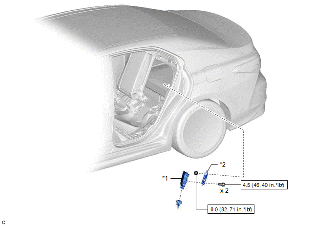
*1 | FUEL PUMP CONTROL ECU |
*2 | FUEL PUMP CONTROL ECU BRACKET |
.png) |
N*m (kgf*cm, ft.*lbf): Specified torque |
- | - |
READ NEXT:
 Removal
REMOVAL CAUTION / NOTICE / HINT
The necessary procedures (adjustment, calibration, initialization or registration) that must be performed after parts are removed and installed, or replaced during fu
Installation
INSTALLATION PROCEDURE 1. INSTALL FUEL PUMP CONTROL ECU BRACKET
(a) Install the fuel pump control ECU bracket to the fuel pump control ECU with the 2 bolts.
Torque: 4.5 N·m {46 kgf·cm, 40 in·l
Components
COMPONENTS ILLUSTRATION
*A for Fold Down Seat Type
- -
*1 REAR CENTER SEAT OUTER BELT ASSEMBLY
*2 REAR SEAT CUSHION ASSEMBLY
*3 REAR SEAT CUSHION LOCK H
SEE MORE:
Air Conditioning Filter
ComponentsCOMPONENTS ILLUSTRATION
*1 AIR FILTER COVER PLATE
*2 CLEAN AIR FILTER
*3 LOWER INSTRUMENT COVER LH
*4 AIR FILTER CASE
*5 AIR FILTER SUB-ASSEMBLY
- - RemovalREMOVAL PROCEDURE
1. REMOVE LOWER INSTRUMENT COVER LH (a) Open the lower
Components
COMPONENTS ILLUSTRATION
*A for 2WD
*B for RH Side
*C for LH Side
- -
*1 NO. 1 FLOOR UNDER COVER
*2 NO. 2 FLOOR UNDER COVER
N*m (kgf*cm, ft.*lbf): Specified torque
- - ILLUSTRATION
*A for 2WD
- -
