Toyota Camry (XV70): Components
COMPONENTS
ILLUSTRATION
|
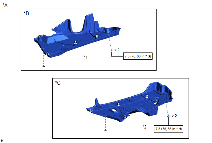
*A | for 2WD |
*B | for RH Side |
|
*C | for LH Side |
- | - |
|
*1 | NO. 1 FLOOR UNDER COVER |
*2 | NO. 2 FLOOR UNDER COVER |
.png) |
N*m (kgf*cm, ft.*lbf): Specified torque |
- | - |
ILLUSTRATION
|
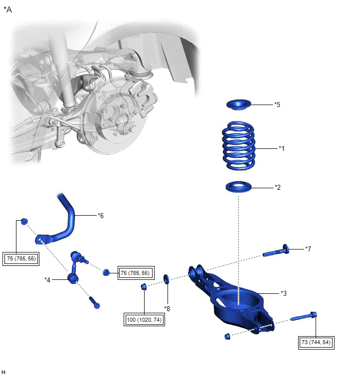
*A | for 2WD |
- | - |
|
*1 | REAR COIL SPRING |
*2 | REAR LOWER COIL SPRING INSULATOR |
|
*3 | REAR NO. 2 SUSPENSION ARM ASSEMBLY |
*4 | REAR STABILIZER LINK ASSEMBLY |
|
*5 | REAR UPPER COIL SPRING INSULATOR |
*6 | REAR STABILIZER BAR |
|
*7 | REAR SUSPENSION TOE ADJUST CAM SUB-ASSEMBLY |
*8 | NO. 2 CAMBER ADJUST CAM |
.png) |
Tightening torque for "Major areas involving basic vehicle performance such as moving/turning/stopping": N*m (kgf*cm, ft.*lbf) |
- | - |
ILLUSTRATION
|
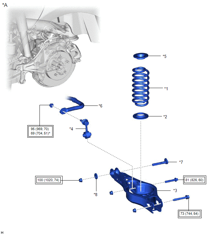
*A | for AWD |
- | - |
|
*1 | REAR COIL SPRING |
*2 | REAR LOWER COIL SPRING INSULATOR |
|
*3 | REAR NO. 2 SUSPENSION ARM ASSEMBLY |
*4 | REAR STABILIZER LINK ASSEMBLY |
|
*5 | REAR UPPER COIL SPRING INSULATOR |
*6 | REAR STABILIZER BAR |
|
*7 | REAR SUSPENSION TOE ADJUST CAM SUB-ASSEMBLY |
*8 | NO. 2 CAMBER ADJUST CAM |
|
|
Tightening torque for "Major areas involving basic vehicle performance such as moving/turning/stopping": N*m (kgf*cm, ft.*lbf) |
- | - |
READ NEXT:
 Removal
REMOVAL CAUTION / NOTICE / HINT
The necessary procedures (adjustment, calibration, initialization, or registration) that must be performed after parts are removed and installed, or replaced during r
Installation
INSTALLATION CAUTION / NOTICE / HINT
HINT:
Use the same procedure for the RH side and LH side.
The following procedure is for the LH side.
PROCEDURE 1. INSTALL REAR UPPER COIL SPRING INS
SEE MORE:
SRS airbags
The SRS airbags inflate when the vehicle is subjected to certain
types of severe impacts that may cause significant injury to the
occupants. They work together with the seat belts to help reduce
the risk of death or serious injury.
SRS front airbags
SRS driver airbag/front passenger airbag
Wireless remote control/electronic key battery
Replace the battery with a new one if it is depleted.
You will need the following items:
Flathead screwdriver
Small flathead screwdriver
Lithium battery CR2032
Replacing the battery
Vehicles without a smart key system
1. Remove the key cover.
To prevent damage to the key,
cover the
