Toyota Camry (XV70): Removal
REMOVAL
CAUTION / NOTICE / HINT
The necessary procedures (adjustment, calibration, initialization, or registration) that must be performed after parts are removed and installed, or replaced during rear coil spring removal/installation are shown below.
Necessary Procedures After Parts Removed/Installed/Replaced|
Replaced Part or Performed Procedure |
Necessary Procedure | Effect/Inoperative Function when Necessary Procedure not Performed |
Link |
|---|---|---|---|
| Rear wheel alignment adjustment |
|
|
|
|
Suspension, tires, etc. (The vehicle height changes because of suspension or tire replacement) |
Rear television camera assembly optical axis (Back camera position setting) |
Parking assist monitor system |
|
| Panoramic view monitor system |
|
HINT:
- Use the same procedure for the RH side and LH side.
- The following procedure is for the LH side.
PROCEDURE
1. REMOVE REAR WHEEL
Click here
.gif)
2. REMOVE NO. 2 FLOOR UNDER COVER (for 2WD)
(a) for LH Side:
Click here
3. REMOVE NO. 1 FLOOR UNDER COVER (for 2WD)
(a) for RH Side:
Click here
4. REMOVE REAR STABILIZER LINK ASSEMBLY
for 2WD: Click here
for AWD: Click here
5. REMOVE REAR COIL SPRING
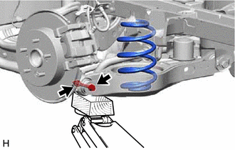
| (a) Place matchmarks on the No. 2 camber adjust cam, rear suspension toe adjust cam sub-assembly and rear suspension member sub-assembly. |
|

(b) Loosen the nut (rear suspension member sub-assembly side) of the rear No. 2 suspension arm assembly.
NOTICE:
Hold the rear suspension toe adjust cam sub-assembly while rotating the nut.
| (c) Using a jack and a wooden block, support the rear No. 2 suspension arm assembly. NOTICE:
|
|
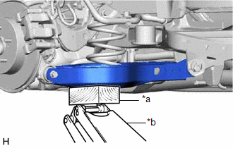
| (d) Remove the bolt and nut, and separate the rear No. 2 suspension arm assembly from the rear axle carrier sub-assembly. NOTICE: Because the nut has its own stopper, do not turn the nut. Loosen the bolt with the nut secured. |
|
(e) Slowly lower the rear No. 2 suspension arm assembly, and then remove the rear coil spring.
6. REMOVE REAR UPPER COIL SPRING INSULATOR
(a) Remove the rear upper coil spring insulator from the vehicle.
7. REMOVE REAR LOWER COIL SPRING INSULATOR
(a) Remove the rear lower coil spring insulator from the rear No. 2 suspension arm assembly.
READ NEXT:
 Installation
INSTALLATION CAUTION / NOTICE / HINT
HINT:
Use the same procedure for the RH side and LH side.
The following procedure is for the LH side.
PROCEDURE 1. INSTALL REAR UPPER COIL SPRING INS
Components
COMPONENTS ILLUSTRATION
*A for 2WD
*B for RH Side
*C for LH Side
- -
*1 NO. 1 FLOOR UNDER COVER
*2 NO. 2 FLOOR UNDER COVER
N*m (k
SEE MORE:
Replacement
REPLACEMENT CAUTION / NOTICE / HINT
CAUTION:
Prolonged and repeated contact with engine oil will result in the removal of natural oils from the skin, leading to dryness, irritation and dermatitis. In addition, used engine oil contains potentially harmful contaminants which may cause skin cance
Removal
REMOVAL CAUTION / NOTICE / HINT
The necessary procedures (adjustment, calibration, initialization, or registration) that must be performed after parts are removed and installed, or replaced during rear axle carrier sub-assembly removal/installation are shown below. Necessary Procedures After Parts
