
Toyota Camry (XV70): Components
COMPONENTS
ILLUSTRATION
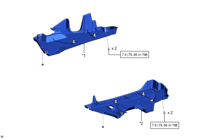
|
*1 | NO. 1 FLOOR UNDER COVER |
*2 | NO. 2 FLOOR UNDER COVER |
 |
N*m (kgf*cm, ft.*lbf): Specified torque |
- | - |
ILLUSTRATION
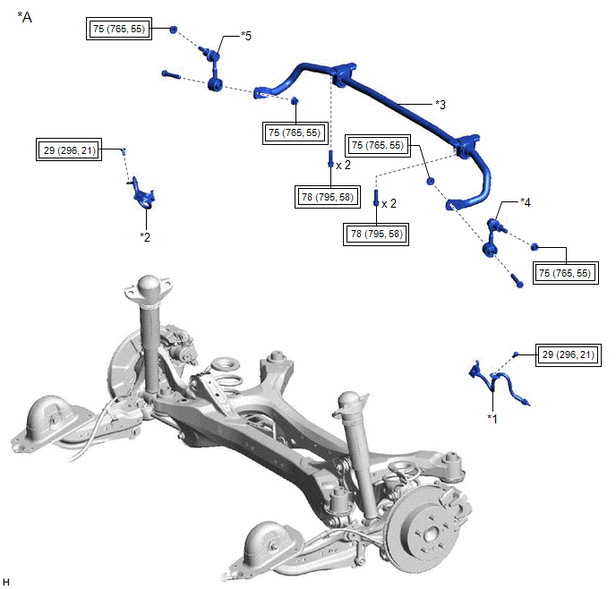
|
*A | w/o Electric Parking Brake System |
- | - |
|
*1 | REAR FLEXIBLE HOSE LH |
*2 | REAR FLEXIBLE HOSE RH |
|
*3 | REAR STABILIZER BAR |
*4 | REAR STABILIZER LINK ASSEMBLY LH |
|
*5 | REAR STABILIZER LINK ASSEMBLY RH |
- | - |
 |
Tightening torque for "Major areas involving basic vehicle performance such as moving/turning/stopping" : N*m (kgf*cm, ft.*lbf) |
- | - |
ILLUSTRATION
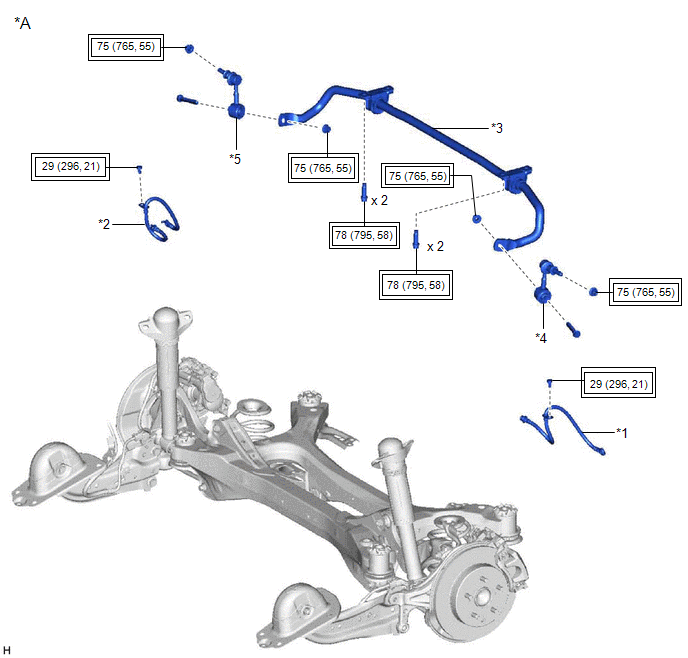
|
*A | w/ Electric Parking Brake System |
- | - |
|
*1 | REAR FLEXIBLE HOSE LH |
*2 | REAR FLEXIBLE HOSE RH |
|
*3 | REAR STABILIZER BAR |
*4 | REAR STABILIZER LINK ASSEMBLY LH |
|
*5 | REAR STABILIZER LINK ASSEMBLY RH |
- | - |
|
|
Tightening torque for "Major areas involving basic vehicle performance such as moving/turning/stopping" : N*m (kgf*cm, ft.*lbf) |
- | - |
ILLUSTRATION
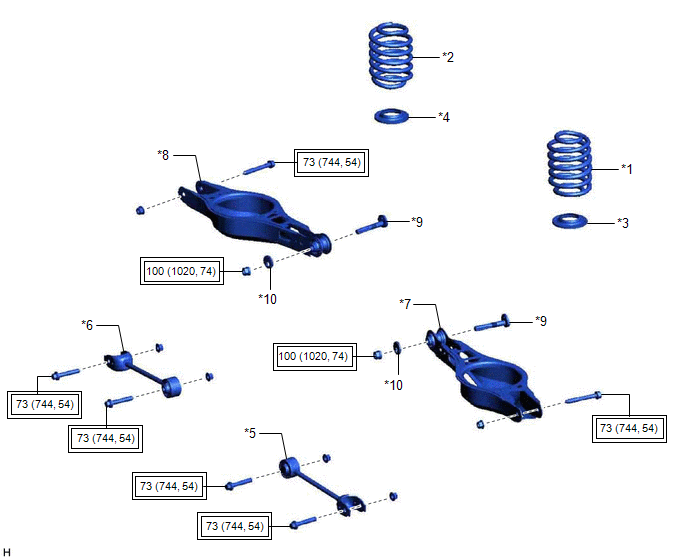
|
*1 | REAR COIL SPRING LH |
*2 | REAR COIL SPRING RH |
|
*3 | REAR LOWER COIL SPRING INSULATOR LH |
*4 | REAR LOWER COIL SPRING INSULATOR RH |
|
*5 | REAR NO. 1 SUSPENSION ARM ASSEMBLY LH |
*6 | REAR NO. 1 SUSPENSION ARM ASSEMBLY RH |
|
*7 | REAR NO. 2 SUSPENSION ARM ASSEMBLY LH |
*8 | REAR NO. 2 SUSPENSION ARM ASSEMBLY RH |
|
*9 | REAR SUSPENSION TOE ADJUST CAM SUB-ASSEMBLY |
*10 | NO. 2 CAMBER ADJUST CAM |
|
|
Tightening torque for "Major areas involving basic vehicle performance such as moving/turning/stopping" : N*m (kgf*cm, ft.*lbf) |
- | - |
ILLUSTRATION
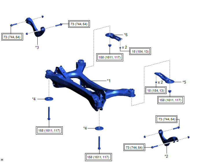
|
*1 | REAR SUSPENSION MEMBER SUB-ASSEMBLY |
*2 | REAR UPPER CONTROL ARM ASSEMBLY LH |
|
*3 | REAR UPPER CONTROL ARM ASSEMBLY RH |
*4 | REAR SUSPENSION MEMBER LOWER STOPPER |
|
*5 | REAR SUSPENSION MEMBER LOWER BRACE LH |
*6 | REAR SUSPENSION MEMBER LOWER BRACE RH |
|
|
Tightening torque for "Major areas involving basic vehicle performance such as moving/turning/stopping" : N*m (kgf*cm, ft.*lbf) |
- | - |
ILLUSTRATION
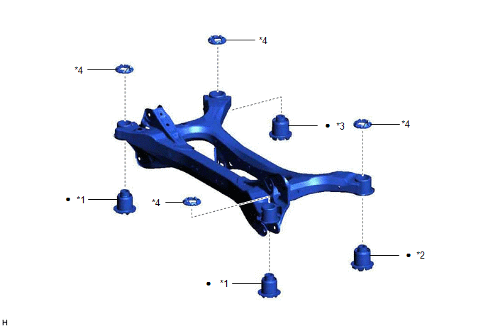
|
*1 | REAR SUSPENSION MEMBER FRONT BODY MOUNTING CUSHION |
*2 | REAR SUSPENSION MEMBER REAR BODY MOUNT CUSHION LH |
|
*3 | REAR SUSPENSION MEMBER REAR BODY MOUNT CUSHION RH |
*4 | REAR SUSPENSION MEMBER CUSHION |
|
● | Non-reusable part |
- | - |
READ NEXT:
 Removal
REMOVAL CAUTION / NOTICE / HINT
The necessary procedures (adjustment, calibration, initialization, or registration) that must be performed after parts are removed and installed, or replaced during r
Installation
INSTALLATION PROCEDURE 1. INSTALL REAR SUSPENSION MEMBER FRONT BODY MOUNTING CUSHION (for LH Side)
(a) Confirm the installation direction and temporarily install a new rear suspension member front b
SEE MORE:
Check Bus 5 Line for Short to GND
DESCRIPTION There may be a short circuit between one of the CAN bus lines and GND when there is no resistance between terminal 15 (CA5H) of the central gateway ECU (network gateway ECU) and terminal 4 (CG) of the DLC3, or terminal 16 (CA5L) of the central gateway ECU (network gateway ECU) and termin
How To Proceed With Troubleshooting
CAUTION / NOTICE / HINT
HINT:
Use the following procedure to troubleshoot the navigation system.
*: Use the Techstream.
PROCEDURE
1. VEHICLE BROUGHT TO WORKSHOP
NEXT
2.
CUSTOMER PROBLEM ANALYSIS
When troubleshooting, check th
