Toyota Camry (XV70): Components
COMPONENTS
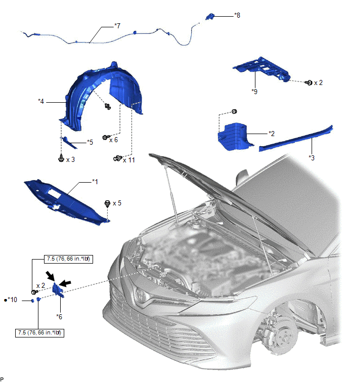
ILLUSTRATION
|
*1 | COOL AIR INTAKE DUCT SEAL |
*2 | COWL SIDE TRIM SUB-ASSEMBLY LH |
|
*3 | FRONT DOOR SCUFF PLATE LH |
*4 | FRONT FENDER LINER LH |
|
*5 | FRONT WHEEL OPENING EXTENSION PAD LH |
*6 | HOOD LOCK ASSEMBLY |
|
*7 | HOOD LOCK CONTROL CABLE ASSEMBLY |
*8 | HOOD LOCK CONTROL LEVER SUB-ASSEMBLY |
|
*9 | NO. 1 INSTRUMENT PANEL UNDER COVER SUB-ASSEMBLY |
*10 | HOOD LOCK NUT CAP |
.png) |
N*m (kgf*cm, ft.*lbf): Specified torque |
● | Non-reusable part |
.png) |
MP grease | - |
- |
READ NEXT:
 Removal
REMOVAL PROCEDURE 1. REMOVE FRONT WHEEL LH
Click here 2. REMOVE FRONT WHEEL OPENING EXTENSION PAD LH
HINT: Use the same procedure as for the RH side. Click here
3. REMOVE FRONT FENDER LIN
Installation
INSTALLATION PROCEDURE 1. INSTALL HOOD LOCK CONTROL CABLE ASSEMBLY
(a) Pass the hood lock control cable assembly into the engine compartment.
(b) Engage the grommet. (c) Engage the 4 clamps to i
SEE MORE:
Reassembly
REASSEMBLY CAUTION / NOTICE / HINT
NOTICE:
When using a vise, place aluminum plates between the part and vise.
When using a vise, do not overtighten it.
HINT:
Use the same procedure for the RH and LH sides.
The procedure listed below is for the LH side.
PROCEDURE 1. INSTAL
On-vehicle Inspection
ON-VEHICLE INSPECTION PROCEDURE
1. REMOVE FRONT WHEEL OPENING EXTENSION PAD RH Click here
2. REMOVE FRONT WHEEL OPENING EXTENSION PAD LH
Click here
3. REMOVE NO. 1 ENGINE UNDER COVER Click here
4. REMOVE NO. 2 ENGINE UNDER COVER ASSEMBLY
Click here
5. CHECK TRAN
© 2023-2026 Copyright www.tocamry.com
