Toyota Camry (XV70): Components
COMPONENTS
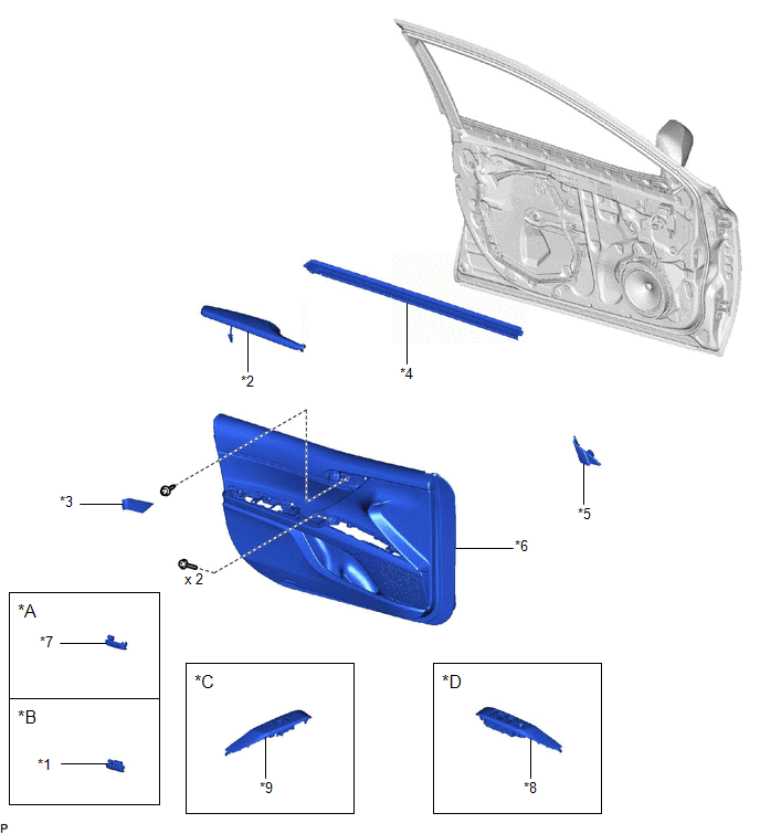
ILLUSTRATION
|
*A | w/o Courtesy Light |
*B | w/ Courtesy Light |
|
*C | for Front Passenger Side |
*D | for Driver Side |
|
*1 | COURTESY LIGHT ASSEMBLY |
*2 | FRONT ARMREST ASSEMBLY |
|
*3 | FRONT DOOR ARMREST COVER SUB-ASSEMBLY |
*4 | FRONT DOOR INNER GLASS WEATHERSTRIP WITH FRONT DOOR VENT SEAL |
|
*5 | FRONT DOOR LOWER FRAME BRACKET GARNISH |
*6 | FRONT DOOR TRIM BOARD SUB-ASSEMBLY |
|
*7 | FRONT DOOR TRIM PLATE |
*8 | MULTIPLEX NETWORK MASTER SWITCH ASSEMBLY WITH FRONT DOOR UPPER ARMREST BASE PANEL |
|
*9 | POWER WINDOW REGULATOR SWITCH ASSEMBLY WITH FRONT DOOR UPPER ARMREST BASE PANEL |
- | - |
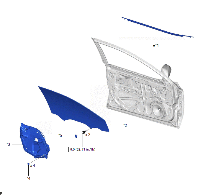
ILLUSTRATION
|
*1 | FRONT DOOR BELT MOULDING ASSEMBLY |
*2 | FRONT DOOR GLASS SUB-ASSEMBLY |
|
*3 | FRONT DOOR SERVICE HOLE COVER |
*4 | FRONT DOOR WEATHERSTRIP CLIP |
|
*5 | HOLE PLUG |
- | - |
.png) |
N*m (kgf*cm, ft.*lbf): Specified torque |
● | Non-reusable part |
READ NEXT:
 Removal
REMOVAL CAUTION / NOTICE / HINT
The necessary procedures (adjustment, calibration, initialization or registration) that must be performed after parts are removed and installed, or replaced during f
Installation
INSTALLATION CAUTION / NOTICE / HINT
HINT:
Use the same procedure for the RH side and LH side.
The following procedure is for the LH side.
PROCEDURE 1. PRECAUTION NOTICE:
After t
SEE MORE:
ECM Power Source Circuit
DESCRIPTION When the engine switch is turned on (IG), the battery voltage is applied to the IGSW terminal of the ECM.
The output signal from the MREL terminal of the ECM causes a current to flow to the coil of the EFI-MAIN NO. 1 relay, closing the contacts and supplying power to terminals +B and +
System Diagram
SYSTEM DIAGRAM ELECTRICAL REMOTE CONTROL MIRROR FUNCTION
MIRROR HEATER FUNCTION
Communication Table
Sender Receiver
Signal Communication Method
Air Conditioning Control Assembly
Air Conditioning Amplifier Assembly
Mirror heater switch (rear window
© 2023-2026 Copyright www.tocamry.com
