Toyota Camry (XV70): Removal
REMOVAL
CAUTION / NOTICE / HINT
The necessary procedures (adjustment, calibration, initialization or registration) that must be performed after parts are removed and installed, or replaced during front door belt moulding removal/installation are shown below.
Necessary Procedure After Parts Removed/Installed/Replaced|
Replaced Part or Performed Procedure |
Necessary Procedure | Effect/Inoperative Function when Necessary Procedure not Performed |
Link |
|---|---|---|---|
|
Disconnect cable from negative battery terminal |
Perform steering sensor zero point calibration |
Lane Tracing Assist System |
|
|
Pre-collision System | |||
|
Memorize steering angle neutral point |
Parking Assist Monitor System |
| |
|
Panoramic View Monitor System |
| ||
|
Front door glass sub-assembly | Initialize power window control system |
|
|
HINT:
- Use the same procedure for the RH side and LH side.
- The following procedure is for the LH side.
PROCEDURE
1. PRECAUTION
NOTICE:
After turning the ignition switch off, waiting time may be required before disconnecting the cable from the negative (-) battery terminal. Therefore, make sure to read the disconnecting the cable from the negative (-) battery terminal notices before proceeding with work.
Click here .gif)
2. DISCONNECT CABLE FROM NEGATIVE BATTERY TERMINAL
for A25A-FKS:
Click here
for 2GR-FKS:
Click here
3. REMOVE FRONT DOOR LOWER FRAME BRACKET GARNISH
Click here
4. REMOVE FRONT DOOR ARMREST COVER SUB-ASSEMBLY
Click here
5. REMOVE MULTIPLEX NETWORK MASTER SWITCH ASSEMBLY WITH FRONT DOOR UPPER ARMREST BASE PANEL (for Driver Side)
Click here
6. REMOVE POWER WINDOW REGULATOR SWITCH ASSEMBLY WITH FRONT DOOR UPPER ARMREST BASE PANEL (for Front Passenger Side)
Click here
7. REMOVE FRONT ARMREST ASSEMBLY
Click here
8. REMOVE FRONT DOOR TRIM PLATE (w/o Courtesy Light)
Click here
9. REMOVE COURTESY LIGHT ASSEMBLY (w/ Courtesy Light)
Click here
10. REMOVE FRONT DOOR TRIM BOARD SUB-ASSEMBLY
Click here
11. REMOVE FRONT DOOR INNER GLASS WEATHERSTRIP WITH FRONT DOOR VENT SEAL
Click here
12. REMOVE FRONT DOOR SERVICE HOLE COVER
Click here
13. REMOVE FRONT DOOR GLASS SUB-ASSEMBLY
Click here
14. REMOVE FRONT DOOR BELT MOULDING ASSEMBLY
(a) Apply protective tape around the front door belt moulding assembly as shown in the illustration.
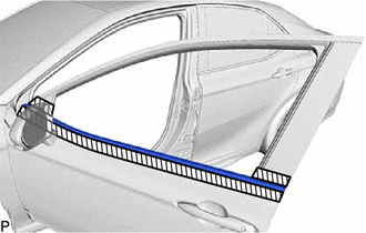
.png) |
Protective Tape |
(b) Disengage the 5 claws as shown in the illustration.
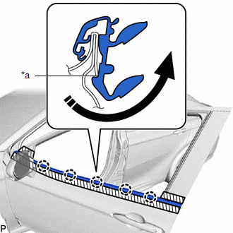
|
*a | Claw |
.png) |
Rotate in this Direction |
(c) Using a thin-bladed screwdriver with its tip wrapped with protective tape, disengage the claw as shown in the illustration.
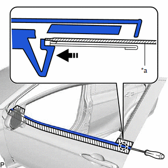
|
*a | Thin-bladed Screwdriver with its Tip Wrapped with Protective Tape |
|
|
Push in this Direction |
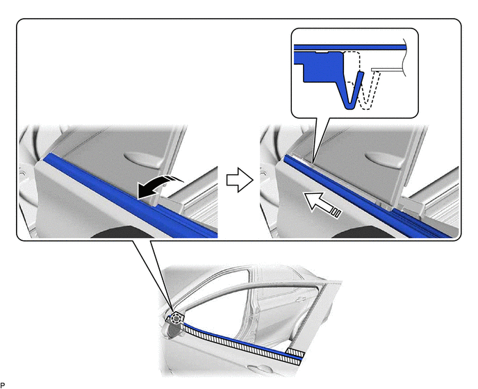
(d) Slightly twist and hold the front door belt moulding assembly in the direction indicated by the arrow (1) shown in the illustration.
|
|
Twist in this Direction (1) |
.png) |
Slide in this Direction (2) |
NOTICE:
If the front door belt moulding assembly is pulled upwards, the claw may break and fall inside the door panel.
(e) Slide the front door belt moulding assembly in the direction indicated by the arrow (2) shown in the illustration to disengage the claw and remove the front door belt moulding assembly.
READ NEXT:
 Installation
INSTALLATION CAUTION / NOTICE / HINT
HINT:
Use the same procedure for the RH side and LH side.
The following procedure is for the LH side.
PROCEDURE 1. PRECAUTION NOTICE:
After t
Components
COMPONENTS ILLUSTRATION
*1 FRONT DOOR GLASS RUN
*2 FRONT DOOR PANEL PROTECTOR
*3 FRONT DOOR REAR WINDOW FRAME MOULDING
*4 FRONT DOOR UPPER WINDOW FRAME MOUL
SEE MORE:
No Sound can be Heard from Speakers
PROCEDURE
1. CHECK AUDIO SETTINGS
(a) In sound output setting mode, set volume, fader and balance to the initial values and check that the sound is normal.
OK: Audio system returns to normal. HINT: Sound quality adjustment measures vary according to the type of amplifier.
OK
Vehicle Control History
VEHICLE CONTROL HISTORY NOTICE: When checking the vehicle control history, first store the output history and then check the history.
VEHICLE CONTROL HISTORY (a) Connect the GTS to the DLC3. (b) Turn the ignition switch to ON.
(c) Enter the following menus: Body Electrical / Clearance Warning /
