
Toyota Camry (XV70): Components
COMPONENTS
ILLUSTRATION
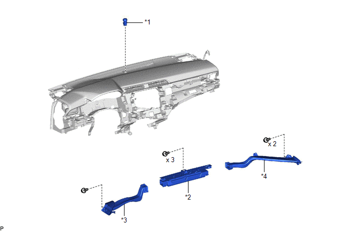
|
*1 | AUTOMATIC LIGHT CONTROL SENSOR |
*2 | DEFROSTER NOZZLE ASSEMBLY |
|
*3 | NO. 1 SIDE DEFROSTER NOZZLE DUCT |
*4 | NO. 2 SIDE DEFROSTER NOZZLE DUCT |
READ NEXT:
 On-vehicle Inspection
ON-VEHICLE INSPECTION PROCEDURE
1. INSPECT AUTOMATIC LIGHT CONTROL SENSOR
*a Front view of wire harness connector
(to Automatic Light Control Sensor)
(a) Disconnect the M1
Removal
REMOVAL CAUTION / NOTICE / HINT
The necessary procedures (adjustment, calibration, initialization, or registration) that must be performed after parts are removed and installed, or replaced during
Installation
INSTALLATION PROCEDURE 1. INSTALL AUTOMATIC LIGHT CONTROL SENSOR
(a) Engage the 2 claws to install the automatic light control sensor.
(b) Connect the connector. 2. INSTALL DEFROSTER NOZZLE ASSE
SEE MORE:
Left Front Wheel Speed Sensor Signal Stuck Low (C050023)
DESCRIPTION Refer to DTC C050012 Click here
DTC No. Detection Item
DTC Detection Condition Trouble Area
C050023 Left Front Wheel Speed Sensor Signal Stuck Low
When the vehicle is driven from 0 km/h to 12 km/h (0 mph to 7 mph), the wheel speed is 1.8 km/h (1.1
Removal
REMOVAL PROCEDURE 1. REMOVE WATER INLET WITH THERMOSTAT SUB-ASSEMBLY
Click here 2. REMOVE V-RIBBED BELT
Click here 3. REMOVE NO. 2 IDLER PULLEY SUB-ASSEMBLY
(a) Remove the bolt and No. 2 idler pulley sub-assembly.
4. REMOVE WATER PUMP PULLEY
(a) Using a screw
© 2023-2026 Copyright www.tocamry.com
