
Toyota Camry (XV70): Compressor Solenoid Circuit (B1451)
DESCRIPTION
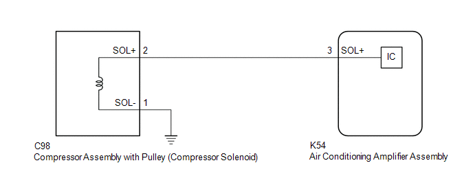
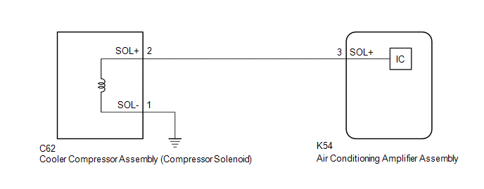
In this circuit, the compressor assembly with pulley (compressor solenoid)*1 or cooler compressor assembly (compressor solenoid)*2 receives refrigerant compression demand signals from the air conditioning amplifier assembly.
Based on this signal, the compressor assembly with pulley (compressor solenoid)*1 or cooler compressor assembly (compressor solenoid)*2 changes the amount of compressor output.
|
DTC No. | Detection Item |
DTC Detection Condition | Trouble Area |
Memory |
|---|---|---|---|---|
| B1451 |
Compressor Solenoid Circuit |
Open or short in compressor solenoid circuit |
| - |
- *1: for A25A-FKS
- *2: for 2GR-FKS
WIRING DIAGRAM
for A25A-FKS
for 2GR-FKS
PROCEDURE
| 1. |
CONFIRM MODEL |
|
Result | Proceed to |
|---|---|
|
for A25A-FKS | A |
|
for 2GR-FKS | B |
| B |
.gif) | GO TO STEP 4 |
|
.gif)
| 2. |
INSPECT AIR CONDITIONING AMPLIFIER ASSEMBLY |
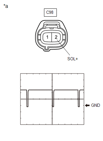
|
*a | Front view of wire harness connector (to Compressor Assembly with Pulley (Compressor Solenoid)) |
(a) Disconnect the C98 compressor assembly with pulley (compressor solenoid) connector.
(b) Connect an oscilloscope to terminal C98-2 (SOL+) and body ground and check the waveform.
OK:
Waveform is similar to that shown in the illustration.
|
Item | Content |
|---|---|
|
Tool Setting | 5 V/DIV., 500 ?s./DIV. |
|
Condition |
|
| OK | | REPLACE COMPRESSOR ASSEMBLY WITH PULLEY (COMPRESSOR SOLENOID)
|
.gif)
|
| 3. |
CHECK HARNESS AND CONNECTOR (COMPRESSOR ASSEMBLY WITH PULLEY (COMPRESSOR SOLENOID) - AIR CONDITIONING AMPLIFIER ASSEMBLY) |
(a) Disconnect the K54 air conditioning amplifier assembly connector.
(b) Measure the resistance according to the value(s) in the table below.
Standard Resistance:
|
Tester Connection | Condition |
Specified Condition |
|---|---|---|
|
C98-2 (SOL+) - K54-3 (SOL+) |
Always | Below 1 ? |
|
C98-2 (SOL+) or K54-3 (SOL+) - Other terminals and body ground |
Always | 10 k? or higher |
| OK | | REPLACE AIR CONDITIONING AMPLIFIER ASSEMBLY |
| NG | | REPAIR OR REPLACE HARNESS OR CONNECTOR |
| 4. |
INSPECT AIR CONDITIONING AMPLIFIER ASSEMBLY |
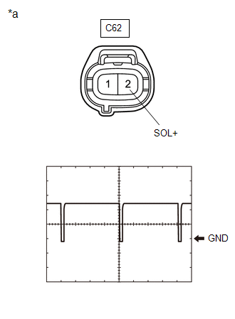
|
*a | Front view of wire harness connector (to Cooler Compressor Assembly (Compressor Solenoid)) |
(a) Disconnect the C62 cooler compressor assembly (compressor solenoid) connector.
(b) Connect an oscilloscope to terminal C62-2 (SOL+) and body ground and check the waveform.
OK:
Waveform is similar to that shown in the illustration.
|
Item | Content |
|---|---|
|
Tool Setting | 5 V/DIV., 500 ?s./DIV. |
|
Condition |
|
| OK | | REPLACE COOLER COMPRESSOR ASSEMBLY (COMPRESSOR SOLENOID)
|
|
| 5. |
CHECK HARNESS AND CONNECTOR (COOLER COMPRESSOR ASSEMBLY (COMPRESSOR SOLENOID) - AIR CONDITIONING AMPLIFIER ASSEMBLY) |
(a) Disconnect the K54 air conditioning amplifier assembly connector.
(b) Measure the resistance according to the value(s) in the table below.
Standard Resistance:
|
Tester Connection | Condition |
Specified Condition |
|---|---|---|
|
C62-2 (SOL+) - K54-3 (SOL+) |
Always | Below 1 ? |
|
C62-2 (SOL+) or K54-3 (SOL+) - Other terminals and body ground |
Always | 10 k? or higher |
| OK | | REPLACE AIR CONDITIONING AMPLIFIER ASSEMBLY |
| NG | | REPAIR OR REPLACE HARNESS OR CONNECTOR |
READ NEXT:
 Communication Malfunction (Bus Ic) (B1497)
DESCRIPTION The air conditioning harness assembly connects the air conditioning amplifier assembly and the servo motors. The air conditioning amplifier assembly supplies power and sends operation inst
Lost Communication with Front Panel LIN (B14B2)
DESCRIPTION The air conditioning control assembly communicates with the air conditioning amplifier assembly via LIN communication.
If a malfunction occurs in the LIN communication system, the air con
Refrigerant Shortage (B14B8)
DESCRIPTION This DTC is stored if the amount of refrigerant in the air conditioning system is insufficient.
The air conditioning amplifier assembly receives the ambient temperature signal, refrigeran
SEE MORE:
Portable Player cannot be Connected Manually/Automatically
CAUTION / NOTICE / HINT HINT: Some versions of "Bluetooth" compatible audio players may not function properly, or the functions may be limited using the radio and display receiver assembly, even if the portable audio player itself can play files.
Click here
PROCEDURE
1.
CHECK C
Installation
INSTALLATION PROCEDURE 1. INSTALL NO. 1 VACUUM HOSE CONNECTOR (for A25A-FKS)
(a) Align the No. 1 vacuum hose connector with the vacuum pump assembly, and push them together until the No. 1 vacuum hose connector makes a "click" sound.
NOTICE:
Check that there is no foreign matter on the conne
