
Toyota Camry (XV70): Communication Malfunction (Bus Ic) (B1497)
DESCRIPTION
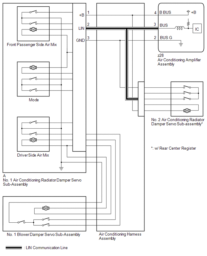
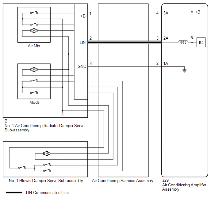
The air conditioning harness assembly connects the air conditioning amplifier assembly and the servo motors. The air conditioning amplifier assembly supplies power and sends operation instructions to each servo motor through the air conditioning harness assembly. Each servo motor sends damper position information to the air conditioning amplifier assembly.
|
DTC No. | Detection Item |
DTC Detection Condition | Trouble Area |
Memory |
|---|---|---|---|---|
| B1497 |
Communication Malfunction (Bus Ic) |
Error or open in communication line |
| Memorized (10 sec. or more)*2 |
- *1: w/ Rear Center Register
- *2: The air conditioning amplifier assembly stores this DTC if the malfunction has occurred for the period of time indicated in the brackets.
WIRING DIAGRAM
for Dual Type
for Single Type
PROCEDURE
| 1. |
CONFIRM MODEL |
|
Result | Proceed to |
|---|---|
|
for Dual Type with Rear Center Register |
A |
| for Dual Type without Rear Center Register |
B |
| for Single Type |
C |
| B |
.gif) | GO TO STEP 7 |
| C |
| GO TO STEP 8 |
|
.gif)
| 2. |
PERFORM ACTIVE TEST USING TECHSTREAM |
(a) Connect the Techstream to the DLC3.
(b) Turn the ignition switch to ON.
(c) Turn the Techstream on.
(d) Enter the following menus: Body Electrical / Air Conditioner / Active test.
(e) Perform the Active Test according to the display on the Techstream.
Body Electrical > Air Conditioner > Active Test|
Tester Display | Measurement Item |
Control Range | Diagnostic Note |
|---|---|---|---|
|
Air Mix Servo Targ Pulse(D) |
No. 1 air conditioning radiator damper servo sub-assembly (driver side air mix) pulse |
Min.: 128 Max.: 383 |
Operates between 165 to 257 pulses |
|
A/O Servo Pulse(Rr D) | No. 2 air conditioning radiator damper servo sub-assembly pulse |
Min.: 128 Max.: 383 |
Operates between 158 to 260 pulses |
|
Tester Display |
|---|
| Air Mix Servo Targ Pulse(D) |
|
Tester Display |
|---|
| A/O Servo Pulse(Rr D) |
|
Result | Proceed to |
|---|---|
|
All of the damper servo motors are malfunctioning |
A |
| One of the damper servo motors is malfunctioning |
B |
| B |
| GO TO STEP 5 |
|
| 3. |
PERFORM ACTIVE TEST USING TECHSTREAM |
(a) Disconnect the No. 1 air conditioning radiator damper servo sub-assembly connector.
(b) Connect the Techstream to the DLC3.
(c) Turn the ignition switch to ON.
(d) Turn the Techstream on.
(e) Enter the following menus: Body Electrical / Air Conditioner / Active test.
(f) Perform the Active Test according to the display on the Techstream.
Body Electrical > Air Conditioner > Active Test|
Tester Display | Measurement Item |
Control Range | Diagnostic Note |
|---|---|---|---|
|
A/O Servo Pulse(Rr D) | No. 2 air conditioning radiator damper servo sub-assembly pulse |
Min.: 128 Max.: 383 |
Operates between 158 to 260 pulses |
|
Tester Display |
|---|
| A/O Servo Pulse(Rr D) |
OK:
The damper servo motor operates smoothly.
| OK | | REPLACE NO. 1 AIR CONDITIONING RADIATOR DAMPER SERVO SUB-ASSEMBLY |
|
| 4. |
INSPECT AIR CONDITIONING AMPLIFIER ASSEMBLY |
NOTICE:
When inspecting the air conditioning amplifier assembly, do not bring the tester probes too close to each other as a short circuit may occur.
(a) Disconnect the z28 air conditioning amplifier assembly connector.
(b) Measure the resistance according to the value(s) in the table below.
Standard Resistance:
|
Tester Connection | Condition |
Specified Condition |
|---|---|---|
|
z28-2 (BUS G) - Body ground |
Always | Below 1 ? |
(c) Measure the voltage according to the value(s) in the table below.
Standard Voltage:
|
Tester Connection | Condition |
Specified Condition |
|---|---|---|
|
z28-4 (B BUS) - Body ground |
Ignition switch ON | 11 to 14 V |
(d) Turn the ignition switch to ON.
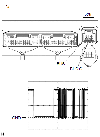
|
*a | Component with harness connected (Air Conditioning Amplifier Assembly) |
(e) Connect an oscilloscope to terminals z28-2 (BUS G) and z28-3 (BUS) of the air conditioning amplifier assembly and check the waveform.
OK:
Waveform is similar to that shown in the illustration.
HINT:
The waveform varies with the blower speed.
|
Item | Content |
|---|---|
|
Tool Setting | 2 V/DIV., 2 ms./DIV. |
|
Condition | Ignition switch ON |
| OK | | REPLACE AIR CONDITIONING HARNESS ASSEMBLY |
| NG | | REPLACE AIR CONDITIONING AMPLIFIER ASSEMBLY |
| 5. |
PERFORM ACTIVE TEST USING TECHSTREAM |
(a) Connect the Techstream to the DLC3.
(b) Turn the ignition switch to ON.
(c) Turn the Techstream on.
(d) Enter the following menus: Body Electrical / Air Conditioner / Active test.
(e) Perform the Active Test according to the display on the Techstream.
Body Electrical > Air Conditioner > Active Test|
Tester Display | Measurement Item |
Control Range | Diagnostic Note |
|---|---|---|---|
|
Air Mix Servo Targ Pulse(D) |
No. 1 air conditioning radiator damper servo sub-assembly (driver side air mix) pulse |
Min.: 128 Max.: 383 |
Operates between 165 to 257 pulses |
|
A/O Servo Pulse(Rr D) | No. 2 air conditioning radiator damper servo sub-assembly pulse |
Min.: 128 Max.: 383 |
Operates between 158 to 260 pulses |
|
Tester Display |
|---|
| Air Mix Servo Targ Pulse(D) |
|
Tester Display |
|---|
| A/O Servo Pulse(Rr D) |
|
Result | Proceed to |
|---|---|
|
Only the No. 1 air conditioning radiator damper servo sub-assembly does not operate |
A |
| Only the No. 2 air conditioning radiator damper servo sub-assembly does not operate |
B |
| B |
| REPLACE AIR CONDITIONING HARNESS ASSEMBLY |
|
| 6. |
INSPECT AIR CONDITIONING HARNESS ASSEMBLY (AIR CONDITIONING AMPLIFIER ASSEMBLY - NO. 1 AIR CONDITIONING RADIATOR DAMPER SERVO SUB-ASSEMBLY) |
(a) Disconnect the z28 air conditioning amplifier assembly connector.
(b) Disconnect the No. 1 air conditioning radiator damper servo sub-assembly connector.
(c) Measure the resistance according to the value(s) in the table below.
Standard Resistance:
|
Tester Connection | Condition |
Specified Condition |
|---|---|---|
|
z28-2 (BUS G) - A-3 (GND) |
Always | Below 1 ? |
|
z28-3 (BUS) - A-2 (LIN) |
Always | Below 1 ? |
|
z28-4 (B BUS) - A-1 (+B) |
Always | Below 1 ? |
| OK | | REPLACE NO. 1 AIR CONDITIONING RADIATOR DAMPER SERVO SUB-ASSEMBLY |
| NG | | REPLACE AIR CONDITIONING HARNESS ASSEMBLY |
| 7. |
INSPECT AIR CONDITIONING HARNESS ASSEMBLY (AIR CONDITIONING AMPLIFIER ASSEMBLY - NO. 1 AIR CONDITIONING RADIATOR DAMPER SERVO SUB-ASSEMBLY) |
(a) Disconnect the z28 air conditioning amplifier assembly connector.
(b) Disconnect the No. 1 air conditioning radiator damper servo sub-assembly connector.
(c) Measure the resistance according to the value(s) in the table below.
Standard Resistance:
|
Tester Connection | Condition |
Specified Condition |
|---|---|---|
|
z28-2 (BUS G) - A-3 (GND) |
Always | Below 1 ? |
|
z28-3 (BUS) - A-2 (LIN) |
Always | Below 1 ? |
|
z28-4 (B BUS) - A-1 (+B) |
Always | Below 1 ? |
| OK | | REPLACE NO. 1 AIR CONDITIONING RADIATOR DAMPER SERVO SUB-ASSEMBLY |
| NG | | REPLACE AIR CONDITIONING HARNESS ASSEMBLY |
| 8. |
INSPECT AIR CONDITIONING HARNESS ASSEMBLY (AIR CONDITIONING AMPLIFIER ASSEMBLY - NO. 1 AIR CONDITIONING RADIATOR DAMPER SERVO SUB-ASSEMBLY) |
(a) Disconnect the z29 air conditioning amplifier assembly connector.
(b) Disconnect the No. 1 air conditioning radiator damper servo sub-assembly connector.
(c) Measure the resistance according to the value(s) in the table below.
Standard Resistance:
|
Tester Connection | Condition |
Specified Condition |
|---|---|---|
|
z29-2 (1A) - B-3 (GND) |
Always | Below 1 ? |
|
z29-3 (2A) - B-2 (LIN) |
Always | Below 1 ? |
|
z29-4 (3A) - B-1 (+B) |
Always | Below 1 ? |
| OK | | REPLACE NO. 1 AIR CONDITIONING RADIATOR DAMPER SERVO SUB-ASSEMBLY |
| NG | | REPLACE AIR CONDITIONING HARNESS ASSEMBLY |
READ NEXT:
 Lost Communication with Front Panel LIN (B14B2)
DESCRIPTION The air conditioning control assembly communicates with the air conditioning amplifier assembly via LIN communication.
If a malfunction occurs in the LIN communication system, the air con
Refrigerant Shortage (B14B8)
DESCRIPTION This DTC is stored if the amount of refrigerant in the air conditioning system is insufficient.
The air conditioning amplifier assembly receives the ambient temperature signal, refrigeran
Refrigerant Overabundance Filling Malfunction (B14BD)
DESCRIPTION This DTC is stored if the amount of refrigerant in the in the air conditioning system exceeds a threshold. The air conditioning amplifier assembly judges whether the amount of refrigerant
SEE MORE:
Disassembly
DISASSEMBLY PROCEDURE 1. REMOVE MAGNET STARTER SWITCH ASSEMBLY
(a) Remove the nut and disconnect the field coil lead wire from the magnet starter switch assembly.
(b) While holding the magnet starter switch assembly to the repair service starter kit, remove the 2 nuts.
Installation
INSTALLATION PROCEDURE 1. INSTALL NO. 2 ECM BRACKET
(a) Install the No. 2 ECM bracket to the ECM with the 2 screws. Torque:
4.5 N·m {46 kgf·cm, 40 in·lbf} 2. INSTALL NO. 1 ECM BRACKET (a) Install the No. 1 ECM bracket to the ECM with the 2 screws.
Torque: 4.5 N·m {46 kgf·cm, 40 in·lbf}
