
Toyota Camry (XV70): Lost Communication with Front Panel LIN (B14B2)
DESCRIPTION
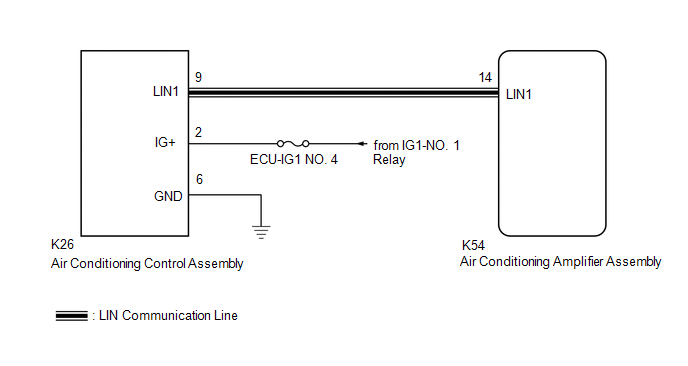
The air conditioning control assembly communicates with the air conditioning amplifier assembly via LIN communication.
If a malfunction occurs in the LIN communication system, the air conditioning amplifier assembly will not operate, even if the air conditioning control assembly is operated.
|
DTC No. | Detection Item |
DTC Detection Condition | Trouble Area |
Memory |
|---|---|---|---|---|
| B14B2 |
Lost Communication with Front Panel LIN |
Lost communication with air conditioning control assembly |
| Memorized (10 sec. or more)* |
- *: The air conditioning amplifier assembly stores this DTC if the malfunction has occurred for the period of time indicated in the brackets.
WIRING DIAGRAM
PROCEDURE
| 1. |
CHECK HARNESS AND CONNECTOR (AIR CONDITIONING CONTROL ASSEMBLY - IG POWER SOURCE) |
(a) Disconnect the K26 air conditioning control assembly connector.
(b) Measure the voltage according to the value(s) in the table below.
Standard Voltage:
|
Tester Connection | Condition |
Specified Condition |
|---|---|---|
|
K26-2 (IG+) - Body ground |
Ignition switch ON | 11 to 14 V |
|
K26-2 (IG+) - Body ground |
Ignition switch off | Below 1 V |
| NG | .gif) | REPAIR OR REPLACE HARNESS OR CONNECTOR |
|
.gif)
| 2. |
CHECK HARNESS AND CONNECTOR (AIR CONDITIONING CONTROL ASSEMBLY - BODY GROUND) |
(a) Measure the resistance according to the value(s) in the table below.
Standard Resistance:
|
Tester Connection | Condition |
Specified Condition |
|---|---|---|
|
K26-6 (GND) - Body ground |
Always | Below 1 ? |
| NG | | REPAIR OR REPLACE HARNESS OR CONNECTOR |
|
| 3. |
CHECK HARNESS AND CONNECTOR (AIR CONDITIONING CONTROL ASSEMBLY - AIR CONDITIONING AMPLIFIER ASSEMBLY) |
(a) Disconnect the K54 air conditioning amplifier assembly connector.
(b) Measure the resistance according to the value(s) in the table below.
Standard Resistance:
|
Tester Connection | Condition |
Specified Condition |
|---|---|---|
|
K26-9 (LIN1) - K54-14 (LIN1) |
Always | Below 1 ? |
|
K26-9 (LIN1) or K54-14 (LIN1) - Other terminals and body ground |
Always | 10 k? or higher |
| NG | | REPAIR OR REPLACE HARNESS OR CONNECTOR |
|
| 4. |
INSPECT AIR CONDITIONING AMPLIFIER ASSEMBLY |
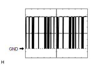
(a) Connect the K54 air conditioning amplifier assembly connector.
(b) Turn the ignition switch to ON.
(c) Using a Techstream, check the waveform.
OK:
Waveform is similar to that shown in the illustration.
|
Item | Content |
|---|---|
|
Terminal No. | K54-14 (LIN1) - Body ground |
|
Tool Setting | 2 V/DIV., 20 ms./DIV. |
|
Condition | Ignition switch ON |
| NG | | REPLACE AIR CONDITIONING AMPLIFIER ASSEMBLY
|
.gif)
|
| 5. |
INSPECT AIR CONDITIONING CONTROL ASSEMBLY |
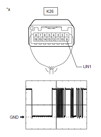
(a) Connect the K26 air conditioning control assembly connector.
(b) Turn the ignition switch to ON.
(c) Using a Techstream, check the waveform.
OK:
Waveform is similar to that shown in the illustration.
|
Item | Content |
|---|---|
|
Terminal No. | K26-9 (LIN1) - Body ground |
|
Tool Setting | 2 V/DIV., 20 ms./DIV. |
|
Condition | Ignition switch ON |
| OK | | REPLACE AIR CONDITIONING AMPLIFIER ASSEMBLY
|
| NG | | REPLACE AIR CONDITIONING CONTROL ASSEMBLY
|
READ NEXT:
 Refrigerant Shortage (B14B8)
DESCRIPTION This DTC is stored if the amount of refrigerant in the air conditioning system is insufficient.
The air conditioning amplifier assembly receives the ambient temperature signal, refrigeran
Refrigerant Overabundance Filling Malfunction (B14BD)
DESCRIPTION This DTC is stored if the amount of refrigerant in the in the air conditioning system exceeds a threshold. The air conditioning amplifier assembly judges whether the amount of refrigerant
Lost Communication With ECM/PCM "A" (U0100-U0142,U0151,U0155)
DESCRIPTION
DTC No. Detection Item
DTC Detection Condition Trouble Area
Memory U0100
Lost Communication With ECM/PCM "A"
No communication with ECM
CAN communica
SEE MORE:
Evaporative Emission System Pressure Sensor/Switch Circuit Short to Ground (P045011,P045015,P04502A,P04502F)
DTC SUMMARY
DTC No. Detection Item
DTC Detection Condition Trouble Area
MIL Memory
Note P045011
Evaporative Emission System Pressure Sensor/Switch Circuit Short to Ground
EVAP pressure less than 42.11 kPa(abs) [6.11 psi(abs)] for 0.5 seconds.
Can
Indicator does not Illuminate
DESCRIPTION If none of the switch indicators on the air conditioning control assembly illuminate, the following suspected areas may be the cause.
Symptom Factor
None of the switch indicators on the air conditioning control assembly illuminate
Air conditioning amplifier assembl
