Toyota Camry (XV70): Removal
REMOVAL
CAUTION / NOTICE / HINT
The necessary procedures (adjustment, calibration, initialization, or registration) that must be performed after parts are removed and installed, or replaced during steering column assembly removal/installation are shown below.
Necessary Procedures After Parts Removed/Installed/Replaced|
Replaced Part or Performed Procedure |
Necessary Procedure | Effect/Inoperative Function when Necessary Procedure not Performed |
Link |
|---|---|---|---|
|
Disconnect cable from negative battery terminal |
Perform steering sensor zero point calibration |
Lane tracing assist system |
|
|
Pre-collision system | |||
|
Memorize steering angle neutral point |
Parking assist monitor system |
| |
|
Panoramic view monitor system |
| ||
|
Steering sensor |
| Parking assist monitor system |
|
|
Steering angle neutral point (Initialize panoramic view monitor system) |
Panoramic view monitor system |
|
PROCEDURE
1. PRECAUTION
Click here .gif)
2. ALIGN FRONT WHEELS FACING STRAIGHT AHEAD
3. REMOVE HORN BUTTON ASSEMBLY
Click here
4. REMOVE STEERING WHEEL ASSEMBLY
Click here
5. REMOVE LOWER STEERING COLUMN COVER SUB-ASSEMBLY
NOTICE:
Removing the lower steering column cover sub-assembly in the incorrect order will cause the parts to break.
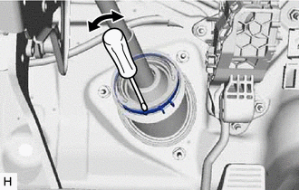
(a) Release the tilt and telescopic lever and fully extend and lower the steering column assembly.
(b) Lock the tilt and telescopic lever.
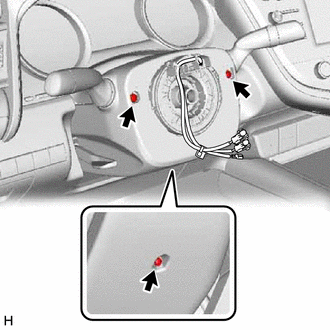
| (c) Remove the 3 screws. |
|
 |
Push Area |
 |
Push in this direction |
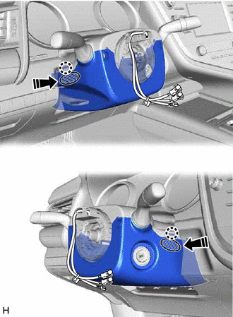
(d) While pressing the push area shown in the illustration to disengage the 2 claws, slightly lower the lower steering column cover sub-assembly.
6. REMOVE UPPER STEERING COLUMN COVER
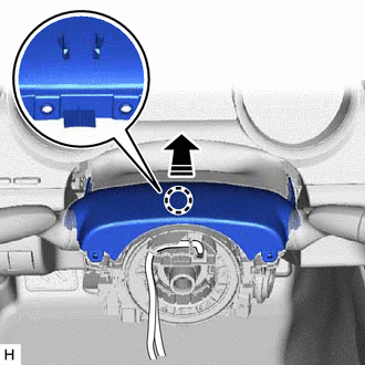
(a) Disengage the claw and separate the upper steering column cover.
|
|
Separate in this direction |
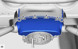
| (b) Disengage the 2 claws and 4 clips to remove the upper steering column cover. |
|
7. REMOVE TRANSPONDER KEY COIL (w/o Smart Key System)
| (a) Disconnect the connector. |
|
(b) Disengage the 2 claws and remove the transponder key coil.
8. REMOVE TURN SIGNAL SWITCH ASSEMBLY WITH SPIRAL CABLE SUB-ASSEMBLY
NOTICE:
- Do not remove/install the spiral cable with sensor sub-assembly with the battery connected and the ignition switch ON.
- Do not rotate the spiral cable with sensor sub-assembly without the steering wheel assembly installed, with the battery connected and the ignition switch ON.
- Ensure that the steering wheel assembly is installed and aligned straight when inspecting the steering sensor.
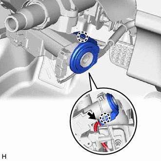
(a) Disconnect each connector from the turn signal switch assembly with spiral cable sub-assembly.
| (b) Using pliers, expand the clamp. |
|
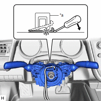
(c) While holding the clamp expanded, raise the claw using a screwdriver to disengage it, and then remove the turn signal switch assembly with spiral cable sub-assembly from the steering column assembly.
9. REMOVE LOWER NO. 1 INSTRUMENT PANEL AIRBAG ASSEMBLY
Click here
10. REMOVE NO. 1 AIR DUCT
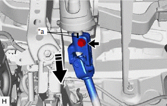
(a) Remove the 2 bolts.
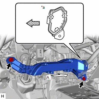
|
*a | View A |
 |
Front |
(b) Disengage the 3 claws to remove the No. 1 air duct.
NOTICE:
Be careful not to deform or damage the lower heater case of the air conditioner unit assembly when removing the No. 1 air duct.
11. REMOVE FRONT WHEEL LH
Click here
12. SEPARATE STEERING INTERMEDIATE SHAFT ASSEMBLY
Click here
13. REMOVE STEERING COLUMN HOLE COVER
(a) Turn back the floor carpet.
| (b) Remove the clip. |
|
(c) Disengage the 2 clips to remove the steering column hole cover.
14. REMOVE STEERING INTERMEDIATE SHAFT ASSEMBLY
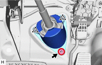
| (a) Using a screwdriver, loosen the clamp as shown in the illustration. |
|
| (b) Remove the bolt and slide the steering intermediate shaft assembly. NOTICE: Do not remove the steering intermediate shaft assembly from the steering column assembly. |
|
(c) Put matchmarks on the steering intermediate shaft assembly and the steering column assembly.
(d) Remove the steering intermediate shaft assembly from the steering column assembly.
15. REMOVE STEERING COLUMN ASSEMBLY
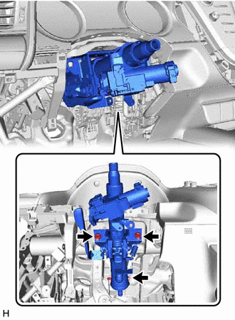
(a) Disconnect each connector and disengage each wire harness clamp from the steering column assembly.
| (b) Remove the bolt, 2 nuts and steering column assembly. |
|
READ NEXT:
 Disassembly
DISASSEMBLY CAUTION / NOTICE / HINT
NOTICE: w/ Smart Key System with Steering Lock Actuator Assembly:
Before replacing the steering lock actuator assembly, refer to Registration.
Click here
Inspection
INSPECTION PROCEDURE 1. INSPECT STEERING COLUMN ASSEMBLY
(a) Check that the 2 bushings are securely installed to the steering column assembly.
If the bushings are deformed, missing or damag
Reassembly
REASSEMBLY PROCEDURE 1. INSTALL IGNITION OR STARTER SWITCH ASSEMBLY (w/o Smart Key System)
(a) Engage the 2 claws to install the ignition or starter switch assembly onto the upper steering column b
SEE MORE:
Identification Information
Vehicle Identification And Serial NumbersVEHICLE IDENTIFICATION AND SERIAL NUMBERS
VEHICLE IDENTIFICATION NUMBER (a) The vehicle identification number is stamped on the vehicle body and on the certification label or name label as shown in the illustration.
*1 Vehicle Identification Nu
Diagnosis System
DIAGNOSIS SYSTEM DESCRIPTION When troubleshooting a vehicle with a diagnosis system, the only difference from the usual troubleshooting procedure is connecting the Techstream to the vehicle and reading various data output from the skid control ECU (brake actuator assembly).
The skid control ECU (b
