Toyota Camry (XV70): Identification Information
Vehicle Identification And Serial Numbers
VEHICLE IDENTIFICATION AND SERIAL NUMBERS
VEHICLE IDENTIFICATION NUMBER
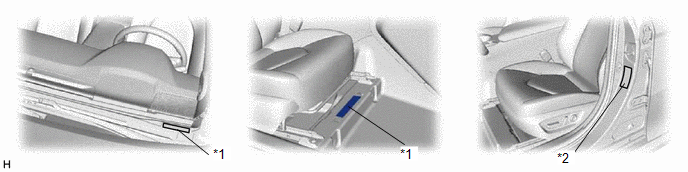
(a) The vehicle identification number is stamped on the vehicle body and on the certification label or name label as shown in the illustration.
|
*1 | Vehicle Identification Number |
*2 | Certification Label or Name Label |
ENGINE SERIAL NUMBER AND TRANSAXLE SERIAL NUMBER
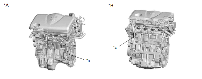
(a) The engine serial number is stamped on the cylinder block of the engine as shown in the illustration.
|
*A | 2GR-FKS |
*B | A25A-FKS |
|
*a | Engine Serial Number |
- | - |
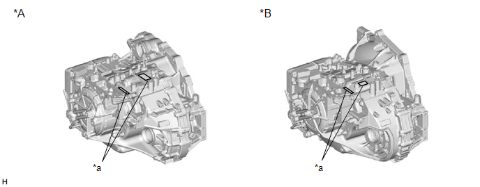
(b) The transaxle serial number is stamped on the transaxle case as shown in the illustration.
|
*A | UA80E |
*B | UB80E, UB80F |
|
*a | Transaxle Serial Number |
- | - |
Vehicle Identification And Serial Numbers
VEHICLE IDENTIFICATION AND SERIAL NUMBERS
VEHICLE IDENTIFICATION NUMBER
(a) The vehicle identification number is stamped on the vehicle body and on the certification label or name label as shown in the illustration.
.png)
|
*1 | Vehicle Identification Number |
*2 | Certification Label or Name Label |
ENGINE SERIAL NUMBER AND TRANSAXLE SERIAL NUMBER
(a) The engine serial number is stamped on the cylinder block of the engine as shown in the illustration.
.png)
|
*A | 2GR-FKS |
*B | A25A-FKS |
|
*a | Engine Serial Number |
- | - |
(b) The transaxle serial number is stamped on the transaxle case as shown in the illustration.
.png)
|
*A | UA80E |
*B | UB80E, UB80F |
|
*a | Transaxle Serial Number |
- | - |
READ NEXT:
 Precaution
PRECAUTION BASIC REPAIR HINT (a) HINTS ON OPERATIONS
1 Attire
Always wear a clean uniform.
A hat and safety shoes must be worn.
2
Vehicle protection Prepare a
Vehicle Lift And Support Locations
VEHICLE LIFT AND SUPPORT LOCATIONS NOTICE ABOUT VEHICLE CONDITION WHEN RAISING VEHICLE
(a) The vehicle must be unloaded before jacking up or raising the vehicle. Never jack up or raise a heavily loa
SEE MORE:
Precaution
PRECAUTION PRECAUTION FOR DISCONNECTING CABLE FROM NEGATIVE BATTERY TERMINAL
NOTICE: When disconnecting the cable from the negative (-) battery terminal, initialize the following systems after the cable is reconnected.
System Name See Procedure
Lane Tracing Assist System
Wheel Speed Sensor Signal Compare Failure (C124E62)
DESCRIPTION The skid control ECU (brake actuator assembly) measures the speed of each wheel by receiving signals from each speed sensor.
These signals are used for recognizing that all four wheels are operating properly.
Therefore, signals from all wheels must be equal.
DTC No. Detection
