Toyota Camry (XV70): Disassembly
Toyota Camry Repair Manual XV70 (2018-2024) / Steering / Steering Gear / Linkage / Steering Gear / Disassembly
DISASSEMBLY
PROCEDURE
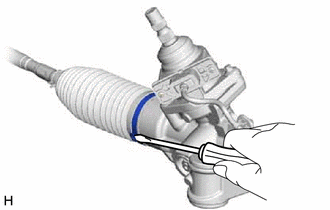
1. REMOVE STEERING RACK BOOT CLIP (for LH Side)
(a) Using pliers, remove the steering rack boot clip.
2. REMOVE STEERING RACK BOOT CLIP (for RH Side)
HINT:
Perform the same procedure as for the LH side.
3. REMOVE NO. 2 STEERING RACK BOOT CLAMP (for LH Side)
| (a) Using a screwdriver, remove the No. 2 steering rack boot clamp. NOTICE: Be careful not to damage the No. 2 steering rack boot. |
|
4. REMOVE NO. 2 STEERING RACK BOOT CLAMP (for RH Side)
HINT:
Perform the same procedure as for the LH side.
5. REMOVE NO. 2 STEERING RACK BOOT
(a) Remove the No. 2 steering rack boot.
NOTICE:
- Check that there is no water, foreign matter or rust inside of the removed No. 2 steering rack boot.
- If there is no water, foreign matter or rust inside of the No. 2 steering rack boot, pull out the rack bar and check for water, foreign matter or rust.
- If water or foreign matter in either part, replace them with a new rack and pinion power steering gear assembly.
- In order to avoid water or foreign matter from adhering to the parts, do not touch the parts unless working in a dust-free, indoors environment.
6. REMOVE NO. 1 STEERING RACK BOOT
HINT:
Perform the same procedure as for the No. 2 steering rack boot.
READ NEXT:
 Inspection
INSPECTION PROCEDURE 1. INSPECT TIE ROD ASSEMBLY LH
(a) Secure the tie rod assembly LH in a vise between aluminum plates.
NOTICE: Do not overtighten the vise.
(b) Instal
Reassembly
REASSEMBLY PROCEDURE 1. INSTALL NO. 2 STEERING RACK BOOT
(a) Apply lithium soap base glycol grease to the inside of the small opening of a new No. 2 steering rack boot.
Lithium
Installation
INSTALLATION PROCEDURE 1. INSTALL STEERING GEAR HEAT INSULATOR (for 2GR-FKS)
(a) Install the steering gear heat insulator to the rack and pinion power steering gear assembly with the 2 bolts in
SEE MORE:
Data List / Active Test
DATA LIST / ACTIVE TEST DATA LIST NOTICE:
In the table below, the values listed under "Normal Condition" are reference values. Do not depend solely on these reference values when deciding whether a part is faulty or not.
HINT: Using the Techstream to read the Data List allows the values or state
Installation
INSTALLATION CAUTION / NOTICE / HINT
HINT:
Use the same procedure for the RH side and LH side.
The following procedure is for the LH side.
PROCEDURE 1. INSTALL REAR AXLE HUB AND BEARING ASSEMBLY
(a) Install the rear axle hub and bearing assembly and rear disc brake dust cover sub-ass
© 2023-2026 Copyright www.tocamry.com
