Toyota Camry (XV70): Inspection
INSPECTION
PROCEDURE
1. INSPECT TIE ROD ASSEMBLY LH
| (a) Secure the tie rod assembly LH in a vise between aluminum plates. NOTICE: Do not overtighten the vise. |
|
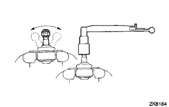
(b) Install the nut to the stud bolt.
(c) Flip the ball joint back and forth 5 times.
(d) Using a torque wrench and the nut, turn the stud bolt continuously at a rate of 2 to 4 seconds per turn, and check the turning torque on the 5th turn.
Standard Turning Torque:
0.49 to 3.43 N*m (5 to 34 kgf*cm, 5 to 30 in.*lbf)
HINT:
If the turning torque is not within the specified range, replace the tie rod assembly LH with a new one.
(e) Check that the dust cover is not cracked and that there is no grease on it.
HINT:
If the dust cover is cracked or there is grease on it, replace the tie rod assembly LH with a new one.
2. INSPECT TIE ROD ASSEMBLY RH
HINT:
Perform the same procedure as for the LH side.
3. INSPECT TOTAL PRELOAD
NOTICE:
Inspect the total preload in a no-load condition by removing the tie rod assemblies RH and LH, and steering rack boots.
| (a) Install SST to the pinion shaft and turn it left and right 5 times or more. SST: 09616-00011 |
|
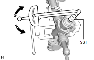
(b) Using SST and a torque wrench, turn the pinion shaft continuously at a rate of 4 to 6 seconds per turn to inspect the total preload of the rack and pinion power steering gear assembly.
Standard Preload:
1.5 to 3.05 N*m (16 to 31 kgf*cm, 14 to 26 in.*lbf)
NOTICE:
Inspect the total preload around the steering rack center position.
HINT:
If the total preload is not within the specified range, replace the rack and pinion power steering gear assembly with a new one.
READ NEXT:
 Reassembly
REASSEMBLY PROCEDURE 1. INSTALL NO. 2 STEERING RACK BOOT
(a) Apply lithium soap base glycol grease to the inside of the small opening of a new No. 2 steering rack boot.
Lithium
Installation
INSTALLATION PROCEDURE 1. INSTALL STEERING GEAR HEAT INSULATOR (for 2GR-FKS)
(a) Install the steering gear heat insulator to the rack and pinion power steering gear assembly with the 2 bolts in
SEE MORE:
Removal
REMOVAL CAUTION / NOTICE / HINT
The necessary procedures (adjustment, calibration, initialization, or registration) that must be performed after parts are removed and installed, or replaced during steering wheel assembly removal/installation are shown below. Necessary Procedures After Parts Remov
Parking Brake Switch Circuit
DESCRIPTION This circuit is from the skid control ECU (brake actuator assembly) to the radio and display receiver assembly. WIRING DIAGRAM
PROCEDURE
1.
CHECK BRAKE WARNING LIGHT (a) Check that the brake warning light comes on when the parking brake is applied and goes off when it is
