
Toyota Camry (XV70): Disassembly
DISASSEMBLY
PROCEDURE
1. REMOVE CONSOLE REAR END PANEL SUB-ASSEMBLY
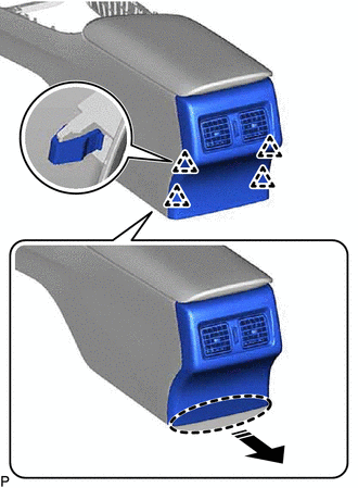
(a) Disengage the 4 clips as shown in the illustration.
.png) |
Place Hand Here |
.png) |
Remove in this Direction |
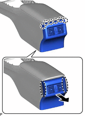
(b) Disengage the 6 claws to remove the console rear end panel sub-assembly as shown in the illustration.
|
|
Place Hand Here |
|
|
Remove in this Direction |
2. REMOVE CONSOLE BOX REGISTER ASSEMBLY (w/ Register)
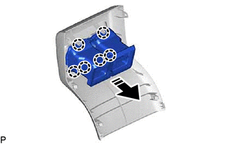
(a) Disengage the 6 claws to remove the console box register assembly as shown in the illustration.
|
|
Remove in this Direction |
3. REMOVE REAR CONSOLE ARMREST ASSEMBLY
| (a) Disengage the 2 guides. |
|
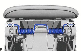
| (b) Remove the E-ring. |
|
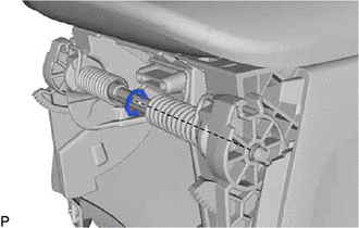
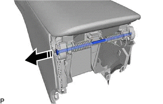
(c) Remove the console compartment door stopper pin as shown in the illustration.
|
|
Remove in this Direction |
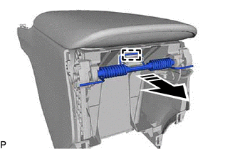
(d) Disengage the guide to remove the console box mount bracket spring and console box spacer as shown in the illustration.
|
|
Remove in this Direction |
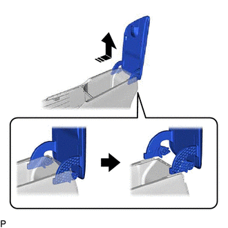
(e) Remove the rear console armrest assembly as shown in the illustration.
|
|
Remove in this Direction |
4. REMOVE CONSOLE COMPARTMENT DOOR PANEL
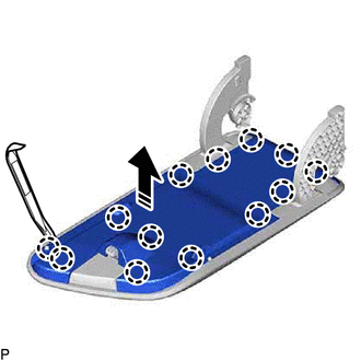
(a) Using a moulding remover, disengage the 13 claws to remove the console compartment door panel as shown in the illustration.
|
|
Remove in this Direction |
5. REMOVE CONSOLE COMPARTMENT DOOR CUSHION
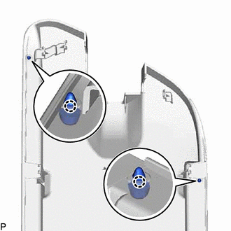
| (a) Disengage the 2 claws to remove the 2 console compartment door cushions. |
|
6. REMOVE CONSOLE COMPARTMENT DOOR LOCK SUB-ASSEMBLY
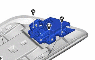
| (a) Remove the 3 screws and console compartment door lock sub-assembly. |
|
7. REMOVE CONSOLE COMPARTMENT DOOR HINGE SUB-ASSEMBLY
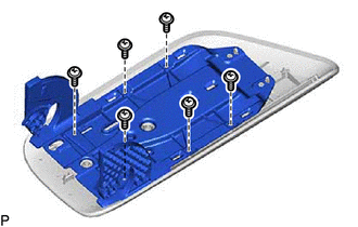
| (a) Remove the 6 screws and console compartment door hinge sub-assembly. |
|
8. REMOVE USB CHARGER SOCKET
Click here
.gif)
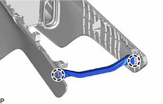
9. REMOVE CONSOLE BOX RETAINER
| (a) Disengage the 2 claws to remove the console box retainer. |
|
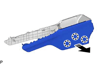
10. REMOVE NO. 2 BOX SIDE PANEL
(a) Disengage the 3 claws as shown in the illustration.
|
|
Remove in this Direction |
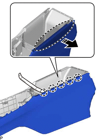
(b) Using a moulding remover, disengage the 5 claws to remove the No. 2 box side panel as shown in the illustration.
|
|
Insert Moulding Remover Here |
|
|
Remove in this Direction |
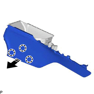
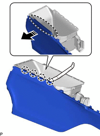
11. REMOVE NO. 1 BOX SIDE PANEL
(a) Disengage the 3 claws as shown in the illustration.
|
|
Remove in this Direction |
(b) Using a moulding remover, disengage the 4 claws to remove the No. 1 box side panel as shown in the illustration.
|
|
Insert Moulding Remover Here |
|
|
Remove in this Direction |
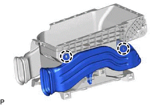
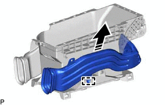
12. REMOVE NO. 3 CONSOLE BOX DUCT (w/ Register)
| (a) Disengage the 2 claws. |
|
(b) Disengage the guide to remove the No. 3 console box duct as shown in the illustration.
|
|
Remove in this Direction |
13. REMOVE NO. 2 CONSOLE BOX DUCT (w/ Register)
| (a) Disengage the 2 claws. |
|
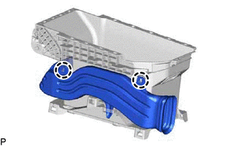
(b) Disengage the guide to remove the No. 2 console box duct as shown in the illustration.
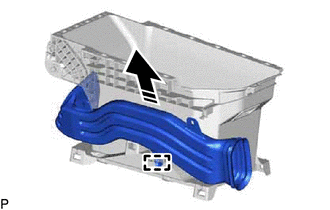
|
|
Remove in this Direction |
READ NEXT:
SEE MORE:
 Portable Player cannot be Connected Manually/Automatically
CAUTION / NOTICE / HINT HINT: Some versions of "Bluetooth" compatible audio players may not function properly, or the functions may be limited using the radio and display receiver assembly, even if the portable audio player itself can play files.
Click here
PROCEDURE
1.
CHECK
Reassembly
REASSEMBLY PROCEDURE 1. INSTALL COOLER DRYER
(a) Using pliers, install a new cooler dryer to the modulator.
*a Modulator
(b) Sufficiently apply compressor oil to 3 O-rings and the fitting surfaces of a new cap.
Compressor Oil: ND-OIL 12 or equivalen
