
Toyota Camry (XV70): Reassembly
REASSEMBLY
PROCEDURE
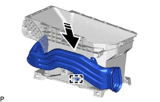
1. INSTALL NO. 2 CONSOLE BOX DUCT (w/ Register)
(a) Engage the guide as shown in the illustration.
.png) |
Install in this Direction |
| (b) Engage the 2 claws to install the No. 2 console box duct. |
|
.png)
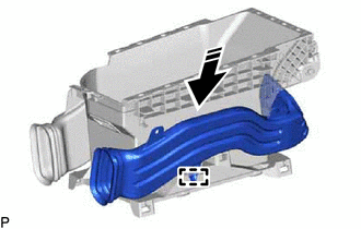
2. INSTALL NO. 3 CONSOLE BOX DUCT (w/ Register)
(a) Engage the guide as shown in the illustration.
|
|
Install in this Direction |
| (b) Engage the 2 claws to install the No. 3 console box duct. |
|
.png)
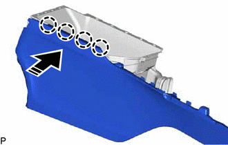
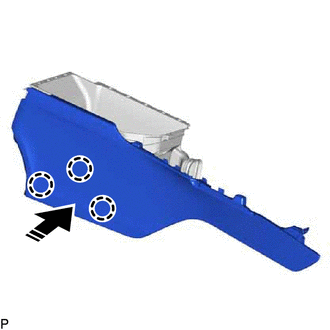
3. INSTALL NO. 1 BOX SIDE PANEL
(a) Engage the 4 claws as shown in the illustration.
|
|
Install in this Direction |
(b) Engage the 3 claws to install the No. 1 box side panel as shown in the illustration.
|
|
Install in this Direction |
4. INSTALL NO. 2 BOX SIDE PANEL
(a) Engage the 5 claws as shown in the illustration.
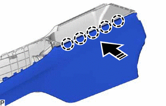
|
|
Install in this Direction |
(b) Engage the 3 claws to install the No. 2 box side panel as shown in the illustration.
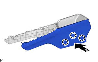
|
|
Install in this Direction |
5. INSTALL CONSOLE BOX RETAINER
| (a) Engage the 2 claws to install the console box retainer. |
|
.png)
6. INSTALL USB CHARGER SOCKET
Click here
.gif)
7. INSTALL CONSOLE COMPARTMENT DOOR HINGE SUB-ASSEMBLY
| (a) Install the console compartment door hinge sub-assembly with the 6 screws. |
|
.png)
8. INSTALL CONSOLE COMPARTMENT DOOR LOCK SUB-ASSEMBLY
| (a) Install the console compartment door lock sub-assembly with the 3 screws. |
|
.png)
9. INSTALL CONSOLE COMPARTMENT DOOR CUSHION
| (a) Engage the 2 claws to install the 2 console compartment door cushions. |
|
.png)
10. INSTALL CONSOLE COMPARTMENT DOOR PANEL
(a) Engage the 13 claws to install the console compartment door panel as shown in the illustration.
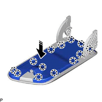
|
|
Install in this Direction |
11. INSTALL REAR CONSOLE ARMREST ASSEMBLY
(a) Insert the rear console armrest assembly as shown in the illustration.
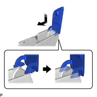
|
|
Install in this Direction |
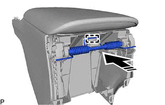
(b) Engage the guide to install the console box mount bracket spring and console box spacer as shown in the illustration.
|
|
Install in this Direction |
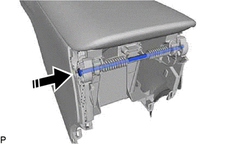
(c) Install the console compartment door stopper pin as shown in the illustration.
|
|
Install in this Direction |
| (d) Install the E-ring. |
|
.png)
| (e) Engage the 2 guides to install the rear console armrest assembly. |
|
.png)
12. INSTALL CONSOLE BOX REGISTER ASSEMBLY (w/ Register)
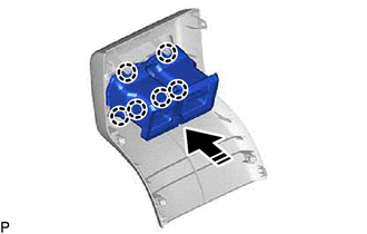
(a) Engage the 6 claws to install the console box register assembly as shown in the illustration.
|
|
Install in this Direction |
13. INSTALL CONSOLE REAR END PANEL SUB-ASSEMBLY
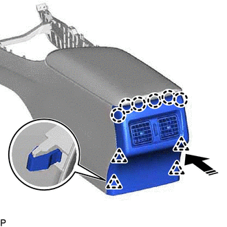
(a) Engage the 6 claws and 4 clips to install the console rear end panel sub-assembly as shown in the illustration.
|
|
Install in this Direction |
READ NEXT:
SEE MORE:
 Removal
REMOVAL CAUTION / NOTICE / HINT
The necessary procedures (adjustment, calibration, initialization, or registration) that must be performed after parts are removed and installed, or replaced during back window glass sub-assembly removal/installation are shown below. Necessary Procedures After Part
Left Rear Wheel Speed Sensor Circuit Voltage Out of Range (C050C1C)
DESCRIPTION Refer to DTC C050C12 Click here
DTC No. Detection Item
DTC Detection Condition Trouble Area
C050C1C Left Rear Wheel Speed Sensor Circuit Voltage Out of Range
When the vehicle is being driven in a straight line at a speed of 20 km/h (12 mph) or more
