
Toyota Camry (XV70): Eco Switch
Components
COMPONENTS
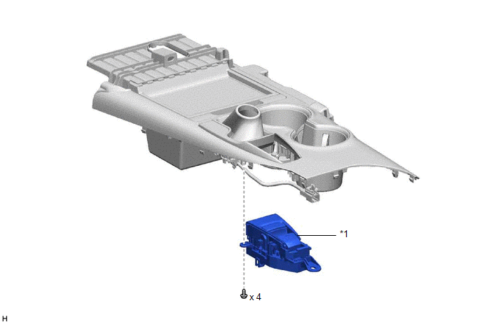
ILLUSTRATION
|
*1 | ECO SWITCH ASSEMBLY (ELECTRIC PARKING BRAKE SWITCH ASSEMBLY) |
- | - |
Removal
REMOVAL
PROCEDURE
1. REMOVE ECO SWITCH ASSEMBLY (ELECTRIC PARKING BRAKE SWITCH ASSEMBLY)
Click here .gif)
Inspection
INSPECTION
PROCEDURE
1. INSPECT ECO SWITCH ASSEMBLY (ELECTRIC PARKING BRAKE SWITCH ASSEMBLY)
|
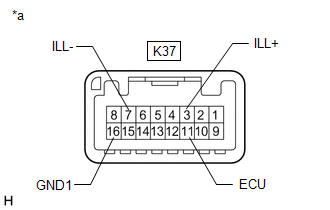
*a | Component without harness connected (ECO Switch Assembly (Electric Parking Brake Switch Assembly)) |
(a) Measure the resistance according to the value(s) in the table below.
Standard Resistance:
|
Tester Connection | Switch Condition |
Specified Condition |
|---|---|---|
|
K37-11 (ECU) - K37-16 (GND1) |
ECO switch assembly (electric parking brake switch assembly) off (switch not pressed) |
100 k? or higher |
|
K37-11 (ECU) - K37-16 (GND1) |
ECO switch assembly (electric parking brake switch assembly) on (switch pressed) |
Below 10 ? |
(b) Check that the switch illuminates.
(1) Battery voltage to the ECO switch assembly (electric parking brake switch assembly) and check that the switch illuminates.
OK:
|
Tester Connection | Specified Condition |
|---|---|
|
Battery positive (+) > 3 (ILL+) Battery negative (-) > 7 (ILL-) |
Illuminates |
Installation
INSTALLATION
PROCEDURE
1. INSTALL ECO SWITCH ASSEMBLY (ELECTRIC PARKING BRAKE SWITCH ASSEMBLY)
Click here .gif)
READ NEXT:
SEE MORE:
 Steering Pad Switch Circuit
DESCRIPTION This circuit sends an operation signal from the steering pad switch assembly to the radio and display receiver assembly.
If there is an open in the circuit, the audio system cannot be operated using the steering pad switch assembly.
If there is a short in the circuit, the same condit
Functions included in LTA system - LTA (Lane Tracing
Assist)
◆ Lane departure alert function
When the system determines
that the vehicle might depart
from its lane or course*, a
warning is displayed on the
multi-information display, and a
warning buzzer will sound to
alert the driver.
When the warning buzzer
sounds, check the area around
your ve
