Toyota Camry (XV70): Emergency Call Switch Illumination Circuit
WIRING DIAGRAM
w/ Sliding Roof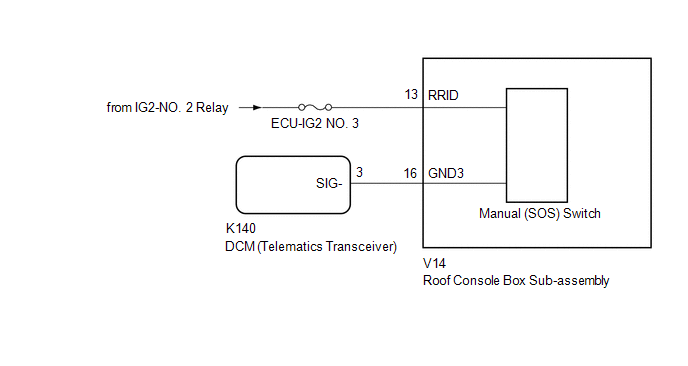 w/o Sliding Roof
CAUTION / NOTICE / HINT
NOTICE:
- Depending on the parts that are replaced during vehicle inspection or maintenance, performing initialization, registration or calibration may be needed. Refer to Precaution for Safety Connect System.
Click here
.gif)
- Inspect the fuses for circuits related to this system before performing the following procedure.
PROCEDURE
|
1. | CONFIRM MODEL |
(a) Choose the model to be inspected.
| Result |
Proceed to |
|---|---|
| w/ Sliding Roof |
A |
| w/o Sliding Roof |
B |
| B |
.gif) | GO TO STEP 4 |
|
.gif)
| 2. |
CHECK HARNESS AND CONNECTOR (ROOF CONSOLE BOX SUB-ASSEMBLY (MANUAL (SOS) SWITCH) POWER SOURCE) |
(a) Disconnect the K140 DCM (telematics transceiver) connector.
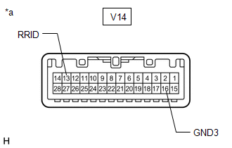
(b) Disconnect the V14 roof console box sub-assembly (manual (SOS) switch) connector.
(c) Measure the voltage according to the value(s) in the table below.
Standard Voltage:
|
Tester Connection | Switch Condition |
Specified Condition |
|---|---|---|
|
V14-13 (RRID) - Body Ground |
Engine switch on (IG) |
11 to 14 V |
(d) Measure the resistance according to the value(s) in the table below.
Standard Resistance:
|
Tester Connection | Condition |
Specified Condition |
|---|---|---|
|
K140-3 (SIG-) - V14-16 (GND3) |
Always | Below 1 Ω |
|
K140-3 (SIG-) or V14-16 (GND3) - Body ground |
Always | 10 kΩ or higher |
| NG | | REPAIR OR REPLACE HARNESS OR CONNECTOR |
|
| 3. |
INSPECT ROOF CONSOLE BOX SUB-ASSEMBLY (MANUAL (SOS) SWITCH) |
| (a) Remove the roof console box sub-assembly (manual (SOS) switch). Click here |
|
(b) Apply battery voltage to the connector and check that the roof console box assembly comes on.
OK:
|
Measurement Condition | Condition |
Specified Condition |
|---|---|---|
|
Battery positive (+) → V14-13 (RRID) Battery negative (-) → V14-16 (GND3) |
Always | Manual (SOS) switch illumination cones on |
| OK | | GO TO STEP 6 |
| NG | | REPLACE ROOF CONSOLE BOX SUB-ASSEMBLY (MANUAL (SOS) SWITCH) |
| 4. |
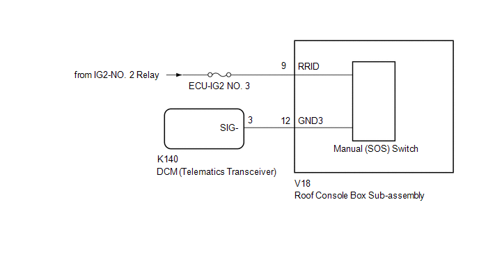
CHECK HARNESS AND CONNECTOR (ROOF CONSOLE BOX SUB-ASSEMBLY (MANUAL (SOS) SWITCH) POWER SOURCE) |
(a) Disconnect the K140 DCM (telematics transceiver) connector.
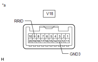
(b) Disconnect the V18 roof console box sub-assembly (manual (SOS) switch) connector.
(c) Measure the voltage according to the value(s) in the table below.
Standard Voltage:
|
Tester Connection | Switch Condition |
Specified Condition |
|---|---|---|
|
V18-9 (RRID) - Body Ground |
Engine switch on (IG) |
11 to 14 V |
(d) Measure the resistance according to the value(s) in the table below.
Standard Resistance:
|
Tester Connection | Condition |
Specified Condition |
|---|---|---|
|
K140-3 (SIG-) - V18-12 (GND3) |
Always | Below 1 Ω |
|
K140-3 (SIG-) or V18-12 (GND3) - Body ground |
Always | 10 kΩ or higher |
| NG | | REPAIR OR REPLACE HARNESS OR CONNECTOR |
|
| 5. |
INSPECT ROOF CONSOLE BOX SUB-ASSEMBLY (MANUAL (SOS) SWITCH) |
| (a) Remove the roof console box sub-assembly (manual (SOS) switch). Click here |
|
(b) Apply battery voltage to the connector and check that the roof console box assembly comes on.
OK:
|
Measurement Condition | Condition |
Specified Condition |
|---|---|---|
|
Battery positive (+) → V18-9 (RRID) Battery negative (-) → V18-13 (GND3) |
Always | Manual (SOS) switch illumination cones on |
| NG | | REPLACE ROOF CONSOLE BOX SUB-ASSEMBLY (MANUAL (SOS) SWITCH) |
|
| 6. |
REPLACE DCM (TELEMATICS TRANSCEIVER) |
(a) Replace the DCM (telematics transceiver) with a new one.
Click here
NOTICE:
- The engine switch must be off.
- Do not exchange the DCM (telematics transceiver) with one from another vehicle.
| NEXT | | PERFORM DCM ACTIVATION |
READ NEXT:
 Telephone And Gps Antenna (for Front Side)
ComponentsCOMPONENTS ILLUSTRATION
*1 INSTRUMENT PANEL SAFETY PAD SUB-ASSEMBLY
*2 NO. 3 HEATER TO REGISTER DUCT SUB-ASSEMBLY
*3 TELEPHONE AND GPS ANTENNA ASSEMBLY
*4
Components
COMPONENTS ILLUSTRATION
*A except Panoramic Moon Roof
- -
*1 TELEPHONE AND GPS ANTENNA ASSEMBLY
*2 TELEPHONE AND GPS ANTENNA ASSEMBLY WITH COVER
*3 COVE
SEE MORE:
System Diagram
SYSTEM DIAGRAM
Transmitting ECU (Transmitter)
Receiving ECU Signal
Communication Method
Skid control ECU (brake actuator assembly)
Steering angle sensor Steering angle sensor request signal
CAN communication line
Steering angle sensor
Customize Parameters
CUSTOMIZE PARAMETERS CUSTOMIZE INTUITIVE PARKING ASSIST SYSTEM
(a) Customizing with the GTS
NOTICE:
When the customer requests a change in a function, first make sure that the function can be customized.
Be sure to make a note of the current settings before customizing.
When trouble
