Toyota Camry (XV70): Fuel Lid Opener does not Operate
DESCRIPTION
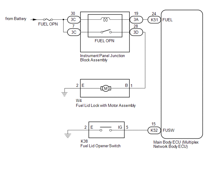
When the fuel lid opener switch is pushed for 0.8 second, the main body ECU (multiplex network ECU) turns on the FUEL OPN relay, and the fuel lid lock with motor assembly opens the fuel lid.
WIRING DIAGRAM
CAUTION / NOTICE / HINT
NOTICE:
- Inspect the fuses for circuits related to this system before performing the following procedure.
- Before replacing the main body ECU (multiplex network body ECU), refer to Registration.
Click here
.gif)
PROCEDURE
|
1. | PERFORM ACTIVE TEST USING TECHSTREAM (FUEL LID OPENER) |
(a) Connect the Techstream to the DLC3.
(b) Turn the ignition switch to ON.
(c) Turn the Techstream on.
(d) Enter the following menus: Body Electrical / Main Body / Active Test.
(e) Perform the Active Test according to the display on the Techstream.
Body Electrical > Main Body > Active Test|
Tester Display | Measurement Item |
Control Range | Diagnostic Note |
|---|---|---|---|
|
Fuel Lid Opener | Fuel lid lock with motor assembly |
OFF/ON | - |
|
Tester Display |
|---|
|
Fuel Lid Opener |
OK:
The fuel lid lock with motor assembly operates normally.
| NG | .gif) |
GO TO STEP 5 |
|
.gif)
|
2. | READ VALUE USING TECHSTREAM (FUEL LID OPENER SWITCH) |
(a) Enter the following menus: Body Electrical / Main Body / Data List.
(b) Read the Data List according to the display on the Techstream.
Body Electrical > Main Body > Data List|
Tester Display | Measurement Item |
Range | Normal Condition |
Diagnostic Note |
|---|---|---|---|---|
|
Fuel Lid Opener Switch |
Fuel lid opener switch status |
OFF or ON | OFF: Fuel lid opener switch not pushed ON: Fuel lid opener switch pushed |
- |
OK:
The Techstream display changes correctly in response to the operation of the fuel lid opener switch.
| OK | |
REPLACE MAIN BODY ECU (MULTIPLEX NETWORK BODY ECU)
|
|
|
3. | INSPECT FUEL LID OPENER SWITCH |
(a) Remove the fuel lid opener switch.
Click here
(b) Inspect the fuel lid opener switch.
Click here
| NG | |
Click here Click here REPLACE FUEL LID OPENER SWITCH |
|
|
4. | CHECK HARNESS AND CONNECTOR (FUEL LID OPENER SWITCH - MAIN BODY ECU (MULTIPLEX NETWORK BODY ECU) AND BODY GROUND) |
(a) Disconnect the K52 main body ECU (multiplex network body ECU) connector.
(b) Measure the resistance according to the value(s) in the table below.
Standard Resistance:
|
Tester Connection | Condition |
Specified Condition |
|---|---|---|
|
K38-5 (IG) - K52-15 (FUSW) |
Always | Below 1 Ω |
|
K38-2 (E) - Body ground |
Always | Below 1 Ω |
|
K38-5 (IG) or K52-15 (FUSW) - Body ground |
Always | 10 kΩ or higher |
| OK | |
REPLACE MAIN BODY ECU (MULTIPLEX NETWORK BODY ECU)
|
| NG | |
REPAIR OR REPLACE HARNESS OR CONNECTOR |
|
5. | INSPECT FUEL LID LOCK WITH MOTOR ASSEMBLY |
(a) Remove the fuel lid lock with motor assembly.
Click here
(b) Inspect the fuel lid lock with motor assembly (motor operation).
Click here
| NG | |
REPLACE FUEL LID LOCK WITH MOTOR ASSEMBLY |
|
|
6. | CHECK HARNESS AND CONNECTOR (INSTRUMENT PANEL JUNCTION BLOCK ASSEMBLY - BATTERY) |
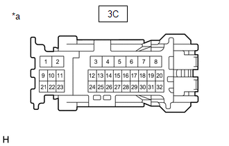
(a) Disconnect the 3C instrument panel junction block assembly connector.
| (b) Measure the voltage according to the value(s) in the table below. Standard Voltage:
|
|
| NG | |
REPAIR OR REPLACE HARNESS OR CONNECTOR |
|
|
7. | CHECK HARNESS AND CONNECTOR (INSTRUMENT PANEL JUNCTION BLOCK ASSEMBLY - MAIN BODY ECU (MULTIPLEX NETWORK BODY ECU)) |
(a) Disconnect the 3A instrument panel junction block assembly connector.
(b) Disconnect the K51 main body ECU (multiplex network body ECU) connector.
(c) Measure the resistance according to the value(s) in the table below.
Standard Resistance:
|
Tester Connection | Condition |
Specified Condition |
|---|---|---|
|
3A-19 - K51-24 (FUEL) |
Always | Below 1 Ω |
|
3A-19 or K51-24 (FUEL) - Body ground |
Always | 10 kΩ or higher |
| NG | |
REPAIR OR REPLACE HARNESS OR CONNECTOR |
|
|
8. | CHECK HARNESS AND CONNECTOR (INSTRUMENT PANEL JUNCTION BLOCK ASSEMBLY - FUEL LID LOCK WITH MOTOR ASSEMBLY) |
(a) Disconnect the 3D instrument panel junction block assembly connector.
(b) Measure the resistance according to the value(s) in the table below.
Standard Resistance:
|
Tester Connection | Condition |
Specified Condition |
|---|---|---|
|
3D-28 - W4-1 (B) |
Always | Below 1 Ω |
|
3D-28 or W4-1 (B) - Body ground |
Always | 10 kΩ or higher |
| NG | |
REPAIR OR REPLACE HARNESS OR CONNECTOR |
|
|
9. | REPLACE INSTRUMENT PANEL JUNCTION BLOCK ASSEMBLY |
(a) Replace the instrument panel junction block assembly.
Click here
|
|
10. | CHECK FUEL LID OPEN OPERATION |
(a) Check that the fuel lid can be opened.
Click here
OK:
The fuel lid can be opened.
| OK | |
END (INSTRUMENT PANEL JUNCTION BLOCK ASSEMBLY WAS DEFECTIVE) |
| NG | |
REPLACE MAIN BODY ECU (MULTIPLEX NETWORK BODY ECU)
|
READ NEXT:
 Components
COMPONENTS ILLUSTRATION
*1 HOOD INSULATOR
*2 HOOD STAY BRACKET RH
*3 HOOD STAY HOLDER
*4 HOOD SUPPORT ASSEMBLY
*5 HOOD TO RADIATOR SUPPORT SEAL
On-vehicle Inspection
ON-VEHICLE INSPECTION PROCEDURE
1. INSPECT HOOD SUB-ASSEMBLY (a) Check that the clearance measurements of areas a through e are within each standard range.
Standard Clearance
Area Meas
SEE MORE:
Parts Location
PARTS LOCATION ILLUSTRATION
*1 FAN WITH MOTOR ASSEMBLY - COOLING FAN MOTOR
- COOLING FAN ECU *2
ECM *3
ENGINE ROOM RELAY BLOCK AND JUNCTION BLOCK ASSEMBLY - EFI-MAIN NO. 1 RELAY
- -
Parts Location
PARTS LOCATION ILLUSTRATION
*A for Type A
*B for Type B
*1 HIGH PITCHED HORN ASSEMBLY
*2 LOW PITCHED HORN ASSEMBLY
*3 HORN RELAY
*4 ENGINE ROOM RELAY BLOCK
- HORN FUSE ILLUSTRATION
*1 SPIRAL CABLE SUB-ASSEMBLY
