
Toyota Camry (XV70): On-vehicle Inspection
Toyota Camry Repair Manual XV70 (2018-2024) / Vehicle Exterior / Door / Hatch / Hood / On-vehicle Inspection
ON-VEHICLE INSPECTION
PROCEDURE
1. INSPECT HOOD SUB-ASSEMBLY
(a) Check that the clearance measurements of areas a through e are within each standard range.
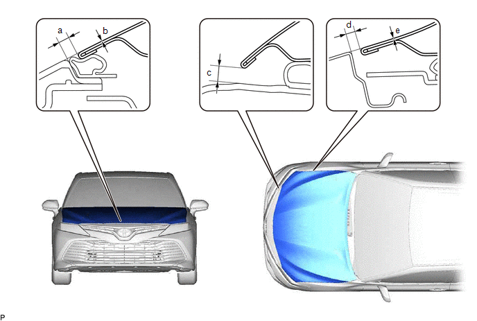 Standard Clearance
 |
Area | Measurement |
Area | Measurement |
|---|---|---|---|
|
a | 2.8 to 6.8 mm (0.110 to 0.268 in.) |
b | -2 to 2 mm (-0.0787 to 0.0787 in.) |
|
c | 5.9 to 9.9 mm (0.232 to 0.390 in.) |
d | 2.5 to 5.5 mm (0.0984 to 0.217 in.) |
|
e | -1.5 to 1.5 mm (-0.0591 to 0.0591 in.) |
- | - |
READ NEXT:
 Disassembly
DISASSEMBLY PROCEDURE 1. REMOVE HOOD TO RADIATOR SUPPORT SEAL
(a) Using a clip remover, disengage the 10 hood to radiator support seal clips to remove the hood to radiator support seal.
Adjustment
ADJUSTMENT CAUTION / NOTICE / HINT
*a Centering Bolt
*b Standard Bolt
HINT:
Centering bolts are used to install the hood hinges and hood lock. The hood and hood
Reassembly
REASSEMBLY PROCEDURE 1. INSTALL HOOD STAY BRACKET RH
(a) Engage the guide.
(b) Install the hood stay bracket RH with the bolt. 2. INSTALL HOOD SUPPORT ASSEMBLY
(a) En
SEE MORE:
Removal
REMOVAL CAUTION / NOTICE / HINT
NOTICE: If both left and right front flexible hoses are disconnected at the same time, be sure to place an identification mark on each hose to indicate its installation position.
HINT:
Use the same procedure for the RH side and LH side.
The following proce
Pressure Control Solenoid "A" Circuit Short to Ground or Open (P074514)
DESCRIPTION Refer to DTC P074512. Click here
DTC No. Detection Item
DTC Detection Condition Trouble Area
MIL Memory
Note P074514
Pressure Control Solenoid "A" Circuit Short to Ground or Open
While the vehicle is being driven so that gear changes occur,
© 2023-2026 Copyright www.tocamry.com
