Toyota Camry (XV70): GVIF Disconnected (from Extension Module to H/U) (B153A)
DESCRIPTION
|
DTC No. | Detection Item |
DTC Detection Condition | Trouble Area |
|---|---|---|---|
|
B153A | GVIF Disconnected (from Extension Module to H/U) |
GVIF disconnected (from navigation ECU to radio and display receiver assembly) |
|
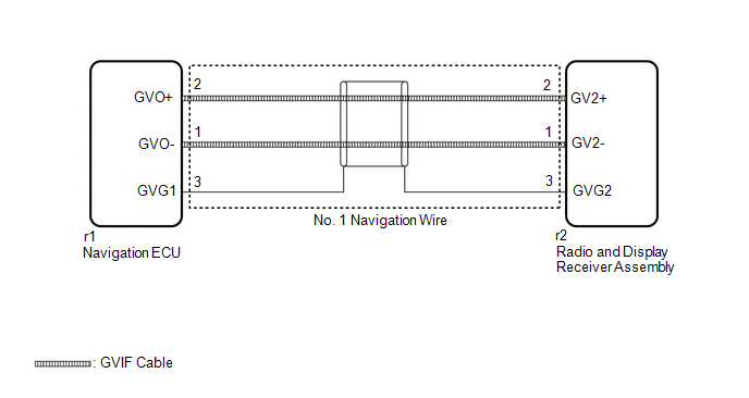
WIRING DIAGRAM
CAUTION / NOTICE / HINT
NOTICE:
- Depending on the parts that are replaced during vehicle inspection or maintenance, performing initialization, registration or calibration may be needed. Refer to Precaution for Navigation System.
Click here
.gif)
- When replacing the radio and display receiver assembly or navigation ECU, always replace it with a new one. If a radio and display receiver assembly or navigation ECU which was installed to another vehicle is used, the following may occur:
- A communication malfunction DTC may be stored.
- The radio and display receiver assembly or navigation ECU may not operate normally.
PROCEDURE
|
1. | CHECK DTC |
(a) Clear the DTCs.
Body Electrical > Navigation System > Clear DTCs(b) Recheck for DTCs and check that no DTCs are output.
Body Electrical > Navigation System > Trouble CodesOK:
No DTCs are output.
| OK | .gif) |
USE SIMULATION METHOD TO CHECK |
|
.gif)
| 2. |
CHECK NO. 1 NAVIGATION WIRE (RADIO AND DISPLAY RECEIVER ASSEMBLY - NAVIGATION ECU) |
| (a) Disconnect the r1 navigation ECU connector. |
|
(b) Disconnect the r2 radio and display receiver assembly connector.
(c) Measure the resistance according to the value(s) in the table below.
Standard Resistance:
|
Tester Connection | Condition |
Specified Condition |
|---|---|---|
|
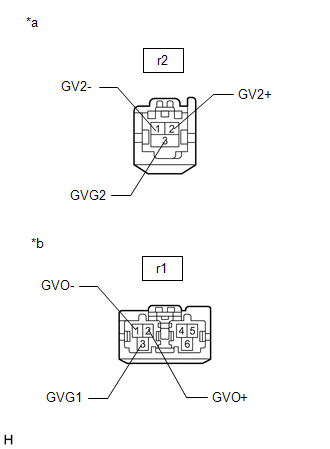
r1-1 (GVO-) - r2-1 (GV2-) |
Always | Below 1 Ω |
|
r1-2 (GVO+) - r2-2 (GV2+) |
Always | Below 1 Ω |
|
r1-3 (GVG1) - r2-3 (GVG2) |
Always | Below 1 Ω |
| NG | | REPLACE NO. 1 NAVIGATION WIRE
|
|
| 3. |
REPLACE NAVIGATION ECU |
(a) Replace the Navigation ECU with a new one.
Click here
|
| 4. |
CHECK DTC |
(a) Clear the DTCs.
Body Electrical > Navigation System > Clear DTCs(b) Recheck for DTCs and check that no DTCs are output.
Body Electrical > Navigation System > Trouble CodesOK:
No DTCs are output.
| OK | |
END (NAVIGATION ECU IS DEFECTIVE) |
| NG | | REPLACE RADIO AND DISPLAY RECEIVER ASSEMBLY
|
READ NEXT:
 Extension Module Disconnected 2 (B1543)
DESCRIPTION If the radio and display receiver assembly cannot detect the navigation ECU for a certain period of time (90 seconds) after the engine switch is turned on (ACC) and the radio and display r
HD Radio Tuner Malfunction (B1551,B158D,B15A0,B15B0,B15B3,B15B7,B15BA,B15F9)
DESCRIPTION These DTCs are stored when a malfunction occurs in the radio and display receiver assembly.
DTC No. Detection Item
DTC Detection Condition Trouble Area
B1551 HD Ra
Extension Module Malfunction 2 (B1556)
DESCRIPTION These DTCs are stored when a malfunction occurs in the Navigation ECU.
DTC No. Detection Item
DTC Detection Condition Trouble Area
B1556 Extension Module Malfuncti
SEE MORE:
Intake Air Temperature Sensor 1 Bank 1 Circuit Short to Ground (P011011)
DESCRIPTION
The intake air temperature sensor, mounted on the mass air flow meter sub-assembly, monitors the intake air temperature. The intake air temperature sensor has a built-in thermistor with a resistance that varies according to the temperature of the intake air. When the intake air temper
Startability Malfunction (P160400)
DESCRIPTION This DTC is stored when the engine does not start even though the STA signal is input or when the engine takes a long time to start, and when the engine speed is low or the engine stalls just after the engine starts.
Using the Techstream, the conditions present when the DTC was stored
