Toyota Camry (XV70): Hazard Warning Switch
Components
COMPONENTS
ILLUSTRATION
|
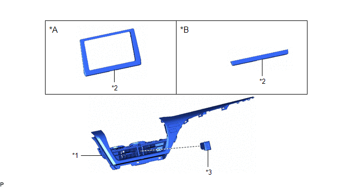
*A | for 7 Inch Display |
*B | for 9 Inch Display |
|
*1 | CENTER INSTRUMENT CLUSTER FINISH PANEL ASSEMBLY |
*2 | CENTER INSTRUMENT CLUSTER FINISH PANEL SUB-ASSEMBLY |
|
*3 | HAZARD WARNING SIGNAL SWITCH ASSEMBLY |
- | - |
Removal
REMOVAL
PROCEDURE
1. REMOVE AIR CONDITIONING CONTROL ASSEMBLY
Click here
.gif)
2. REMOVE CENTER INSTRUMENT CLUSTER FINISH PANEL SUB-ASSEMBLY (for 7 Inch Display)
Click here
3. REMOVE CENTER INSTRUMENT CLUSTER FINISH PANEL SUB-ASSEMBLY (for 9 Inch Display)
Click here
4. REMOVE CENTER INSTRUMENT CLUSTER FINISH PANEL ASSEMBLY
Click here
5. REMOVE HAZARD WARNING SIGNAL SWITCH ASSEMBLY
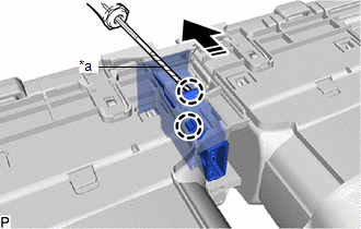
(a) Using a screwdriver with its tip wrapped with protective tape, disengage the 2 claws and remove the hazard warning signal switch assembly as shown in the illustration.
|
*a | Protective Tape |
.png) |
Remove in this Direction |
Inspection
INSPECTION
PROCEDURE
1. INSPECT HAZARD WARNING SIGNAL SWITCH ASSEMBLY
| (a) Measure the resistance according to the value(s) in the table below. Standard Resistance:
If the result is not as specified, replace the hazard warning signal switch assembly. |
|
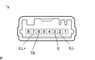
(b) Illumination Inspection
(1) Apply battery voltage to the hazard warning signal switch assembly and check that the switch illuminates.
OK:
|
Condition | Specified Condition |
|---|---|
|
Battery positive (+) → Terminal 7 (ILL+) Battery negative (-) → Terminal 2 (ILL-) |
Illuminates |
If the result is not as specified, replace the hazard warning signal switch assembly.
Installation
INSTALLATION
PROCEDURE
1. INSTALL HAZARD WARNING SIGNAL SWITCH ASSEMBLY
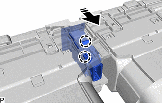
(a) Engage the 2 claws to install the hazard warning signal switch assembly.
.png) |
Install in this Direction |
2. INSTALL CENTER INSTRUMENT CLUSTER FINISH PANEL ASSEMBLY
Click here .gif)
3. INSTALL CENTER INSTRUMENT CLUSTER FINISH PANEL SUB-ASSEMBLY (for 7 Inch Display)
Click here
4. INSTALL CENTER INSTRUMENT CLUSTER FINISH PANEL SUB-ASSEMBLY (for 9 Inch Display)
Click here
5. INSTALL AIR CONDITIONING CONTROL ASSEMBLY
Click here
READ NEXT:
 Components
COMPONENTS ILLUSTRATION
*1 HEADLIGHT ASSEMBLY
- -
N*m (kgf*cm, ft.*lbf): Specified torque
- - ILLUSTRATION
*A for LED Type Turn Sig
Removal
REMOVAL CAUTION / NOTICE / HINT
The necessary procedures (adjustment, calibration, initialization or registration) that must be performed after parts are removed and installed, or replaced during h
SEE MORE:
Precaution
PRECAUTION PRECAUTION FOR DISCONNECTING CABLE FROM NEGATIVE BATTERY TERMINAL
NOTICE: When disconnecting the cable from the negative (-) battery terminal, initialize the following systems after the cable is reconnected.
System Name See Procedure
Lane Tracing Assist System
Inspection
INSPECTION PROCEDURE 1. INSPECT CAMSHAFT TIMING GEAR BOLT
(a) Check the stroke of the plunger in the center of the camshaft timing gear bolt.
Standard Stroke: 2.2 mm (0.0866 in.) or more HINT: When pressing the plunger, there may be a stepped feeling. This is not a malfunction.
If the r
