
Toyota Camry (XV70): Removal
REMOVAL
CAUTION / NOTICE / HINT
The necessary procedures (adjustment, calibration, initialization or registration) that must be performed after parts are removed and installed, or replaced during headlight assembly removal/installation are shown below.
Necessary Procedure After Parts Removed/Installed/Replaced|
Replaced Part or Performed Procedure |
Necessary Procedure | Effect/Inoperative Function when Necessary Procedure not Performed |
Link |
|---|---|---|---|
| *1: Applies only for when removing and installing or replacing the rear television camera assembly. | |||
| Front bumper assembly (w/ Panoramic view monitor system) |
Front television camera view adjustment |
Panoramic view monitor system |
|
Replacement or removal and installation of 2 or more parts:
|
| ||
HINT:
- Use the same procedure for the RH side and LH side.
- The following procedure is for the LH side.
PROCEDURE
1. REMOVE FRONT BUMPER ASSEMBLY
Click here .gif)
2. REMOVE HEADLIGHT ASSEMBLY
(a) Apply protective tape around the headlight assembly as shown in the illustration.
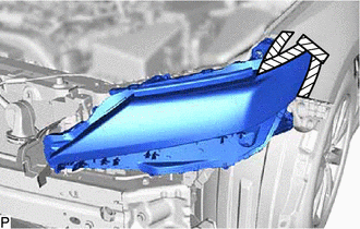
.png) |
Protective Tape |
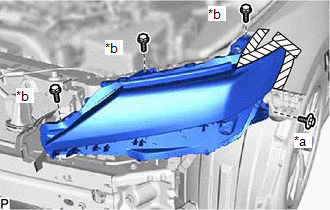
| (b) Remove the bolt and 3 screws. |
|
(c) Disengage the guide to separate the headlight assembly as shown in the illustration.
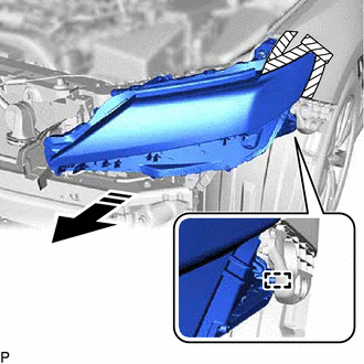
.png) |
Remove in this Direction |
(d) for Bulb Type Turn Signal Light:
(1) Disengage the clamp.
(e) Disconnect each connector to remove the headlight assembly.
READ NEXT:
 Disassembly
DISASSEMBLY CAUTION / NOTICE / HINT
HINT:
Use the same procedure for the RH side and LH side.
The following procedure is for the LH side.
PROCEDURE 1. REMOVE FRONT TURN SIGNAL LIGHT
Inspection
INSPECTION PROCEDURE 1. INSPECT HEADLIGHT ASSEMBLY LH (for Bulb Type Turn Signal Light)
*a Component without harness connected
(Headlight Assembly LH) (a) Apply battery voltage
Adjustment
ADJUSTMENT CAUTION / NOTICE / HINT
HINT:
Use the same procedure for the RH side and LH side.
The following procedure is for the LH side.
PROCEDURE 1. PREPARE VEHICLE FOR HEADLIGHT A
SEE MORE:
Installation
INSTALLATION CAUTION / NOTICE / HINT
NOTICE:
Immediately after installing the brake pads, the braking performance may be reduced. Always perform a road test in a safe place while paying attention to the surroundings.
After replacing the rear disc brake pads, the brake pedal may feel soft
Back-up Light Bulb
ReplacementREPLACEMENT CAUTION / NOTICE / HINT
HINT:
Use the same procedure for the RH side and LH side.
The following procedure is for the LH side.
PROCEDURE 1. REMOVE LUGGAGE COMPARTMENT DOOR COVER
Click here
2. REMOVE BACK-UP LIGHT BULB
Click here 3. INSTALL BACK-
