
Toyota Camry (XV70): Components
COMPONENTS
ILLUSTRATION
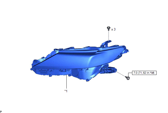
|
*1 | HEADLIGHT ASSEMBLY |
- | - |
.png) |
N*m (kgf*cm, ft.*lbf): Specified torque |
- | - |
ILLUSTRATION
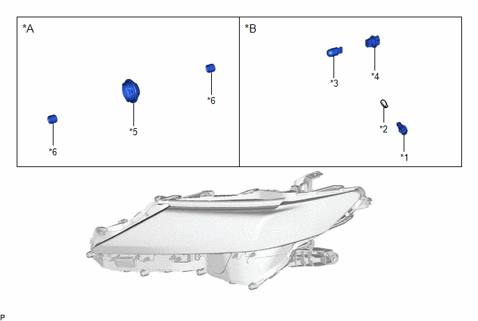
|
*A | for LED Type Turn Signal Light |
*B | for Bulb Type Turn Signal Light |
|
*1 | FRONT MARKER LIGHT SOCKET PLUG |
*2 | FRONT SIDE MARKER LIGHT BULB |
|
*3 | FRONT TURN SIGNAL LIGHT BULB |
*4 | FRONT TURN SIGNAL LIGHT SOCKET |
|
*5 | HEADLIGHT BACK COVER |
*6 | HEADLIGHT COVER |
READ NEXT:
 Removal
REMOVAL CAUTION / NOTICE / HINT
The necessary procedures (adjustment, calibration, initialization or registration) that must be performed after parts are removed and installed, or replaced during h
Disassembly
DISASSEMBLY CAUTION / NOTICE / HINT
HINT:
Use the same procedure for the RH side and LH side.
The following procedure is for the LH side.
PROCEDURE 1. REMOVE FRONT TURN SIGNAL LIGHT
Inspection
INSPECTION PROCEDURE 1. INSPECT HEADLIGHT ASSEMBLY LH (for Bulb Type Turn Signal Light)
*a Component without harness connected
(Headlight Assembly LH) (a) Apply battery voltage
SEE MORE:
Removal
REMOVAL CAUTION / NOTICE / HINT
The necessary procedures (adjustment, calibration, initialization or registration) that must be performed after parts are removed and installed, or replaced during rear door belt moulding removal/installation are shown below. Necessary Procedure After Parts Removed
Installation
INSTALLATION PROCEDURE 1. INSTALL NO. 1 SWITCH WIRE
HINT: Perform this procedure only when replacement of the No. 1 switch wire is necessary.
(a) Engage the 2 guides to install the No. 1 switch wire to the steering wheel assembly.
2. INSTALL SHIFT PADDLE SWITCH (TRANSMISSION SHIFT SWITCH ASSEM
© 2023-2026 Copyright www.tocamry.com
