Toyota Camry (XV70): Initialization Switch Error (for Test Diagnosis) (C2198)
DESCRIPTION
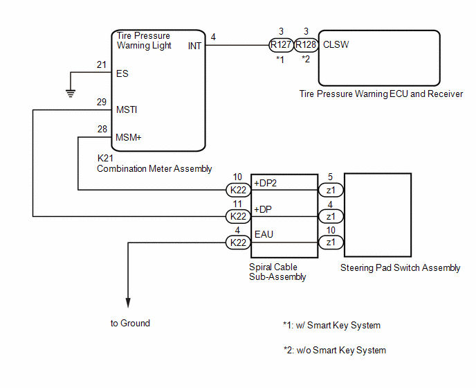
The switch circuit inside the combination meter assembly turns on and off according to the steering pad switch assembly operation.
During test mode, the tire pressure warning light blinks at 0.125 second intervals when "Set Pressure" is selected on the multi-information display, and illuminates when the "OK" switch (steering pad switch assembly) is pressed.
|
DTC No. | Detection Item |
DTC Detection Condition | Trouble Area |
Note |
|---|---|---|---|---|
| C2198 |
Initialization Switch Error (for Test Diagnosis) |
Test mode procedure is performed. |
| - |
WIRING DIAGRAM
CAUTION / NOTICE / HINT
NOTICE:
- When replacing the tire pressure warning ECU and receiver, read the transmitter IDs and number of the transmitters (4 or 5) stored in the old ECU using the Techstream and write them down before removal.
- It is necessary to perform initialization
.gif) after registration
of the transmitter IDs into the tire pressure warning ECU and receiver if the ECU has been replaced.
after registration
of the transmitter IDs into the tire pressure warning ECU and receiver if the ECU has been replaced.
PROCEDURE
|
1. | INSPECT STEERING PAD SWITCH ASSEMBLY |
(a) Remove the steering pad switch assembly.
Click here
(b) Inspect the steering pad switch assembly.
Click here
| NG | .gif) | REPLACE STEERING PAD SWITCH ASSEMBLY |
|
.gif)
| 2. |
INSPECT SPIRAL CABLE SUB-ASSEMBLY |
(a) Remove the spiral cable sub-assembly.
Click here
(b) Inspect the spiral cable sub-assembly.
Click here
| NG | | REPLACE SPIRAL CABLE SUB-ASSEMBLY |
|
| 3. |
CHECK HARNESS AND CONNECTOR (SPIRAL CABLE SUB-ASSEMBLY - COMBINATION METER ASSEMBLY) |
(a) Disconnect the K22 spiral cable sub-assembly connector.
(b) Disconnect the K21 combination meter assembly connector.
(c) Measure the resistance according to the value(s) in the table below.
Standard Resistance:
|
Tester Connection | Condition |
Specified Condition |
|---|---|---|
|
K22-10 (+DP2) - K21-28 (MSM+) |
Always | Below 1 Ω |
|
K22-10 (+DP2) or K21-28 (MSM+) - Body ground |
Always | 10 kΩ or higher |
|
K22-11 (+DP) - K21-29 (MSTI) |
Always | Below 1 Ω |
|
K22-11 (+DP) or K21-29 (MSTI) - Body ground |
Always | 10 kΩ or higher |
| NG | | REPAIR OR REPLACE HARNESS OR CONNECTOR |
|
| 4. |
CHECK HARNESS AND CONNECTOR (COMBINATION METER ASSEMBLY - TIRE PRESSURE WARNING ECU AND RECEIVER) |
(a) Disconnect the R127 or R128 tire pressure warning ECU and receiver connector.
(b) Disconnect the K21 combination meter assembly connector.
(c) Measure the resistance according to the value(s) in the table below.
Standard Resistance:
w/ Smart Key System|
Tester Connection | Condition |
Specified Condition |
|---|---|---|
|
R127-3 (CLSW) - K21-4 (INT) |
Always | Below 1 Ω |
|
R127-3 (CLSW) or K21-4 (INT) - Body ground |
Always | 10 kΩ or higher |
|
K21-21 (ES) - Body ground |
Always | Below 1 Ω |
|
Tester Connection | Condition |
Specified Condition |
|---|---|---|
|
R128-3 (CLSW) - K21-4 (INT) |
Always | Below 1 Ω |
|
R128-3 (CLSW) or K21-4 (INT) - Body ground |
Always | 10 kΩ or higher |
|
K21-21 (ES) - Body ground |
Always | Below 1 Ω |
| NG | | REPAIR OR REPLACE HARNESS OR CONNECTOR |
|
| 5. |
CHECK TERMINAL VOLTAGE (INT) |
(a) Connect the R127 or R128 tire pressure warning ECU and receiver connector.
(b) Disconnect the K21 combination meter assembly connector.
(c) Measure the voltage according to the value(s) in the table below.
Standard Voltage:
|
Tester Connection | Condition |
Specified Condition |
|---|---|---|
|
K21-4 (INT) - Body ground |
Ignition switch ON | 8 to 15 V |
| OK | | GO TO METER / GAUGE SYSTEM |
| NG | | REPLACE TIRE PRESSURE WARNING ECU AND RECEIVER |
READ NEXT:
 Lost Communication with Brake System Control Module (U0129)
DESCRIPTION The tire pressure warning ECU and receiver receives signals from the skid control ECU (brake actuator assembly) via CAN communication system.
DTC No. Detection Item
DTC Detect
Tire Pressure Warning Light Circuit
DESCRIPTION If the tire pressure warning ECU and receiver detects any problems, the tire pressure warning light blinks for 1 minute then illuminates, and tire pressure monitoring is disabled at the sa
Tire Position Not Identified
DESCRIPTION The tire pressure warning ECU and receiver identifies the tire position for each tire pressure warning valve and transmitter according to the wheel speed signals from the skid control ECU
SEE MORE:
Removal
REMOVAL CAUTION / NOTICE / HINT
The necessary procedures (adjustment, calibration, initialization, or registration) that must be performed after parts are removed and installed, or replaced during spark plug removal/installation are shown below. Necessary Procedures After Parts Removed/Installed/R
Water Pump
ComponentsCOMPONENTS ILLUSTRATION
*1 ENGINE WATER PUMP ASSEMBLY (WATER INLET HOUSING)
*2 GASKET
N*m (kgf*cm, ft.*lbf): Specified torque
● Non-reusable part RemovalREMOVAL CAUTION / NOTICE / HINT
The necessary procedures (adjustment, calibration,
