Toyota Camry (XV70): Inspection
INSPECTION
PROCEDURE
1. INSPECT FRONT DRIVE SHAFT ASSEMBLY
| (a) Check that there is no excessive play in the radial direction of the outboard joint. |
|
.png)
(b) Check that the inboard joint slides smoothly in the thrust direction.
(c) Check that there is no excessive play in the radial direction of the inboard joint.
(d) Check the boots for damage.
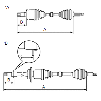
| (e) Check whether the drive shaft dimension (A) and (B) are within specification. NOTICE: Keep the drive shaft assembly level during inspection. Dimension (A):
Dimension (B):
|
| ||||||||||||||||||||||
READ NEXT:
 Reassembly
REASSEMBLY CAUTION / NOTICE / HINT
HINT:
Use the same procedure for the RH side and LH side.
The following procedure is for the LH side.
PROCEDURE 1. INSTALL FRONT DRIVE SHAFT BEARING (f
Installation
INSTALLATION CAUTION / NOTICE / HINT
HINT:
Use the same procedure for the RH side and LH side.
The following procedure is for the LH side.
PROCEDURE 1. INSTALL FRONT DRIVE SHAFT HOLE SNA
SEE MORE:
Headlight Dimmer Switch Circuit
DESCRIPTION The steering sensor receives the following switch information:
Light control switch in DRL OFF*, tail, head or AUTO position
Dimmer switch in high, low or high flash (pass) position
*: w/ DRL OFF Switch
WIRING DIAGRAM
CAUTION / NOTICE / HINT
NOTICE: Be
Disassembly
DISASSEMBLY CAUTION / NOTICE / HINT
HINT:
Use the same procedure for the RH side and LH side.
The following procedure is for the LH side.
PROCEDURE 1. SEPARATE FRONT NO. 2 AXLE INBOARD JOINT BOOT CLAMP
(a) Secure the drive shaft in a vise between aluminum plates. NOTICE:
Do not ove
© 2023-2026 Copyright www.tocamry.com
