Toyota Camry (XV70): Inspection
INSPECTION
PROCEDURE
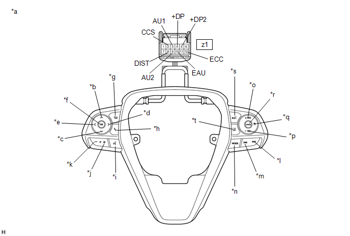
1. INSPECT STEERING PAD SWITCH ASSEMBLY
(a) Measure the resistance according to the value(s) in the table below.
|
*a | Component without harness connected (Steering Pad Switch Assembly) |
*b | Up |
|
*c | Down |
*d | Right |
|
*e | Left |
*f | OK |
|
*g | Back |
*h | On/off Hook |
|
*i | Voice |
*j | Volume+ |
|
*k | Volume- |
*l | Seek+ |
|
*m | Seek- |
*n | MODE |
|
*o | +RES |
*p | -SET |
|
*q | Cruise Control Main |
*r | CANCEL |
|
*s | Distance Control |
*t | Lane Departure Alert |
Standard Resistance:
|
Tester Connection | Condition |
Specified Condition |
|---|---|---|
|
z1-3 (AU1) - z1-10 (EAU) |
No switch pushed |
95 to 105 kΩ |
|
Seek+ switch pushed |
Below 2.5 Ω | |
|
Seek- switch pushed |
313 to 345 Ω | |
|
Volume+ switch pushed |
950 to 1050 Ω | |
|
Volume- switch pushed |
2955 to 3265 Ω | |
|
z1-9 (AU2) - z1-10 (EAU) |
No switch pushed |
95 to 105 kΩ |
|
MODE switch pushed |
Below 2.5 Ω | |
|
On/off hook switch pushed |
950 to 1050 Ω | |
|
Voice switch pushed |
2955 to 3265 Ω | |
|
z1-5 (+DP2) - z1-10 (EAU) |
No switch pushed |
95 to 105 kΩ |
|
Left switch pushed |
Below 2.5 Ω | |
|
Up switch pushed |
313 to 345 Ω | |
|
Down switch pushed |
950 to 1050 Ω | |
|
Right switch pushed |
2955 to 3265 Ω | |
|
z1-4 (+DP) - z1-10 (EAU) |
No switch pushed |
95 to 105 kΩ |
|
OK switch pushed |
Below 2.5 Ω | |
|
Back switch pushed |
313 to 345 Ω | |
|
z1-8 (DIST) - z1-12 (ECC) |
No switch pushed |
1 MΩ or higher |
|
Distance control switch pushed |
Below 2.5 Ω | |
|
Lane departure alert switch pushed |
228 to 252 Ω | |
|
z1-2 (CCS) - z1-12 (ECC) |
No switch pushed |
1 MΩ or higher |
|
Cruise control main switch pushed |
Below 2.5 Ω | |
|
CANCEL switch pushed |
228 to 252 Ω | |
|
+RES switch pushed |
599 to 661 Ω | |
|
-SET switch pushed |
1463 to 1617 Ω |
HINT:
If the result is not as specified, replace the steering pad switch assembly.
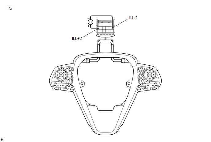
(b) Check the illumination.
|
*a | Component without harness connected (Steering Pad Switch Assembly) |
- | - |
(1) Connect a positive (+) lead from the battery to terminal 1 (ILL+2) and a negative (-) lead to terminal 6 (ILL-2) of the steering pad switch assembly connector.
(2) Check that the steering pad switch assembly illumination illuminates.
OK:
The steering pad switch assembly illumination illuminates.
HINT:
If the result is not as specified, replace the steering pad switch assembly.
READ NEXT:
 Installation
INSTALLATION PROCEDURE 1. INSTALL STEERING PAD SWITCH ASSEMBLY
(a) Engage the 4 claws and 3 pins to install the steering pad switch assembly.
(b) Install the 2 screws. (c) Connect the steering p
Precaution
PRECAUTION HANDLING PRECAUTIONS FOR STEERING SYSTEM
(a) Care must be taken when replacing parts. Incorrect replacement may affect the performance of the steering system and result in a driving haza
SEE MORE:
Removal
REMOVAL CAUTION / NOTICE / HINT
The necessary procedures (adjustment, calibration, initialization or registration) that must be performed after parts are removed and installed, or replaced during fuel sender gauge assembly removal/installation are shown below. Necessary Procedures After Parts Remo
How To Proceed With Troubleshooting
CAUTION / NOTICE / HINT
HINT:
Use the following procedure to troubleshoot the air conditioning system.
*: Use the Techstream.
PROCEDURE
1. VEHICLE BROUGHT TO WORKSHOP
NEXT
2.
CUSTOMER PROBLEM ANALYSIS
HINT:
In troubleshooting, confirm that
