Toyota Camry (XV70): Removal
REMOVAL
CAUTION / NOTICE / HINT
CAUTION:
If the luggage compartment door support assembly is removed, the luggage compartment door will slam shut. Make sure to support the luggage compartment door by hand when it is open and when opening and closing it.
PROCEDURE
1. REMOVE SPARE WHEEL COVER ASSEMBLY
| (a) Remove the spare wheel cover assembly. |
|
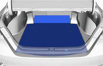
2. REMOVE SPARE WHEEL COVER TRAY
| (a) Remove the spare wheel cover tray. |
|
3. REMOVE NO. 1 LUGGAGE COMPARTMENT TRIM HOOK
(a) Disengage the claw and guide to remove the No. 1 luggage compartment trim hook as shown in the illustration.
.png) |
Push |
HINT:
Use the same procedure for the RH side and LH side.
4. REMOVE LUGGAGE COMPARTMENT DOOR STRIKER COVER
(a) Disengage the 2 claws to remove the luggage compartment door striker cover as shown in the illustration.
.png) |
Remove in this Direction |
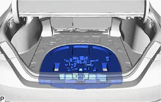
5. REMOVE REAR FLOOR FINISH PLATE
| (a) Remove the 4 clips. |
|
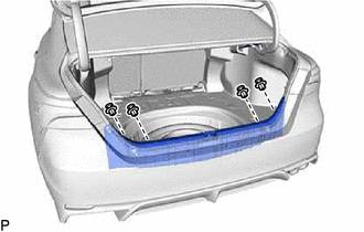
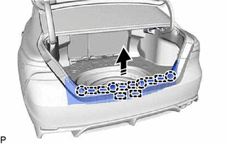
(b) Disengage the 4 claws and 8 guides to remove the rear floor finish plate as shown in the illustration.
|
|
Remove in this Direction |
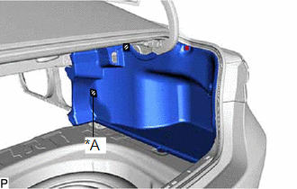
6. REMOVE LUGGAGE COMPARTMENT TRIM INNER COVER RH
| (a) Using a clip remover, remove the clip (A). |
|
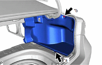
(b) Remove the clip (B).
(c) Disengage each fastener to remove the luggage compartment trim inner cover RH.
|
*A | w/ Fastener |
.png) |
Fastener |
7. REMOVE LUGGAGE COMPARTMENT TRIM INNER COVER LH
| (a) Using a clip remover, remove the clip (A). |
|
(b) Remove the clip (B).
(c) Disengage each fastener to remove the luggage compartment trim inner cover LH.
|
*A | w/ Fastener |
|
|
Fastener |
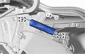
8. REMOVE BACK DOOR STAY SPRING
| (a) Disengage the 2 guides to remove the back door stay spring. HINT: Use the same procedure for the RH side and LH side. |
|
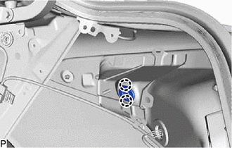
9. REMOVE BACK DOOR LOCK UPPER BUSH
| (a) Disengage the 2 claws to remove the back door lock upper bush. HINT: Use the same procedure for the RH side and LH side. |
|
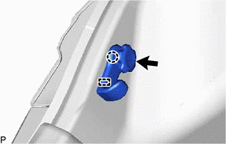
10. REMOVE LUGGAGE COMPARTMENT DOOR SUPPORT ASSEMBLY
NOTICE:
- Avoid touching the piston rod as much as possible to prevent foreign matter from attaching to it. Be sure to hold the cylinder while servicing.
- Do not wear cotton gloves or other similar materials when handling the piston rod. Fibers may attach to the rod and result in gas leaks.
- Do not apply any horizontal load to the luggage compartment door support assembly in order to prevent the piston rod from deforming.
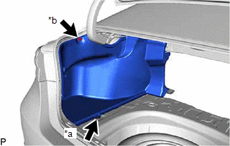
(a) Using a screwdriver with its tip wrapped with protective tape, slightly raise the stop ring as indicated by the arrows, in the order shown in the illustration.
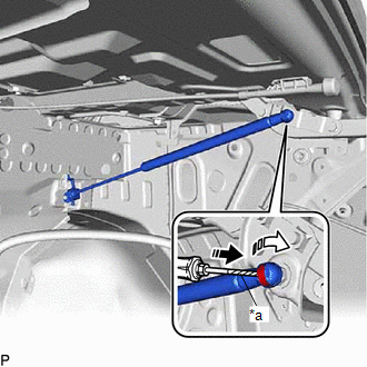
|
*a | Protective Tape |
|
|
Remove in this Direction (1) |
.png) |
Remove in this Direction (2) |
NOTICE:
- Do not remove the stop rings from the luggage compartment door support assembly. Raise the stop ring just enough to allow the ball joint to be disengaged.
- Do not reuse the luggage compartment door support assembly if the stop ring has been removed.
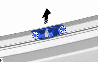
(b) Disengage the ball joint.
NOTICE:
Remove the luggage compartment door support assembly while supporting the luggage door by hand.
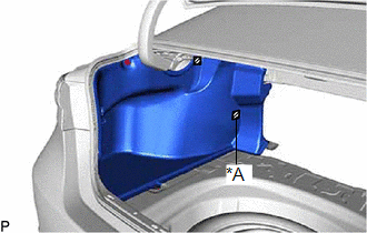
(c) Disengage the guide as indicated by the arrows, in the order shown in the illustration to remove the luggage compartment door support assembly.
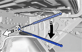
|
|
Remove in this Direction (1) |
|
|
Remove in this Direction (2) |
READ NEXT:
 Installation
INSTALLATION CAUTION / NOTICE / HINT
CAUTION: After installing the luggage compartment door support assembly, use your hand to open and close the luggage door. Make sure the luggage door can open a
Disposal
DISPOSAL PROCEDURE 1. DISPOSE OF LUGGAGE COMPARTMENT DOOR SUPPORT ASSEMBLY
(a) Secure the luggage compartment door support assembly horizontally in a vise with the piston rod pulled out.
Luggage Compartment Door Weatherstrip
ComponentsCOMPONENTS ILLUSTRATION
*1 LUGGAGE COMPARTMENT DOOR WEATHERSTRIP
*2 REAR FLOOR FINISH PLATE
*3 SPARE WHEEL COVER ASSEMBLY
*4 SPARE WHEEL COVER TRA
SEE MORE:
Disassembly
DISASSEMBLY PROCEDURE 1. REMOVE OIL PUMP RELIEF VALVE
(a) Using a 27 mm socket wrench, remove the oil pump relief valve plug from the oil pump cover.
(b) Remove the oil pump relief valve spring and oil pump relief valve from the valve hole.
2. REMOVE OIL PUMP COVER
If the electronic key does
not operate properly (vehicles with a smart key system)
If communication between the electronic key and vehicle is
interrupted or the electronic key cannot be used
because the battery is depleted, the smart key system and wireless
remote control cannot be used. In such cases, the doors
and trunk can be opened and the engine can be started by followin
