Toyota Camry (XV70): Inspection
INSPECTION
PROCEDURE
1. INSPECT REAR STABILIZER LINK ASSEMBLY
(a) Inspect the turning torque of the ball joint.
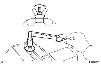
(1) Secure the rear stabilizer link assembly in a vise using aluminum plates.
NOTICE:
Do not overtighten the vise.
(2) Install the nut to the rear stabilizer link assembly stud.
(3) Move the stud back and forth several times. Using a torque wrench, turn the stud continuously at a rate of 3 to 5 seconds per turn and take the torque reading on the 5th turn.
Standard Turning Torque:
0.05 to 1.96 N*m (0.6 to 19 kgf*cm, 0.5 to 17 in.*lbf)
HINT:
If the turning torque is not within the specified range, replace the rear stabilizer link assembly with a new one.
(4) Turn the stud to check that the stud does not catch and there is no play.
HINT:
If the stud catches or there is play while turning, replace the rear stabilizer link assembly with a new one.
(b) Inspect the dust cover.
(1) Check that the dust cover is not cracked and that there is no grease on it.
HINT:
If the dust cover is cracked or there is grease on it, replace the rear stabilizer link assembly with a new one.
READ NEXT:
 Installation
INSTALLATION PROCEDURE 1. INSTALL REAR STABILIZER BUSHING
(a) Install the 2 rear stabilizer bushings to the rear stabilizer bar.
NOTICE: Be sure to install the rear stabilizer bushings so that eac
Components
COMPONENTS ILLUSTRATION
*1 REAR LOWER STABILIZER BRACKET
*2 REAR NO. 1 STABILIZER BAR BRACKET
*3 REAR STABILIZER BAR
*4 REAR STABILIZER BUSHING
*5 REAR
SEE MORE:
Fuel Rail Pressure Sensor (Low) Signal Stuck in Range (P107A2A,P107A64)
DESCRIPTION Refer to DTC P107A11. Click here
DTC No. Detection Item
DTC Detection Condition Trouble Area
MIL Memory
Note P107A2A
Fuel Rail Pressure Sensor (Low) Signal Stuck in Range
When target low pressure side fuel pressure changes, the change in fue
Removal
REMOVAL CAUTION / NOTICE / HINT
The necessary procedures (adjustment, calibration, initialization or registration) that must be performed after parts are removed and installed, or replaced during flow shutting valve (No. 1 water by-pass hose) removal/installation are shown below. Necessary Procedu
