
Toyota Camry (XV70): Installation
Toyota Camry Repair Manual XV70 (2018-2024) / General / Maintenance / Front Brake Flexible Hose / Installation
INSTALLATION
CAUTION / NOTICE / HINT
NOTICE:
- Because the left and right front flexible hoses are not interchangeable, verify the part number when installing the front flexible hoses.
- When reusing the front flexible hoses, use the identification marks created during removal to install each front flexible hose to its original position.
HINT:
- Use the same procedure for the RH side and LH side.
- The following procedure is for the LH side.
PROCEDURE
1. INSTALL FRONT FLEXIBLE HOSE
NOTICE:
When installing the front flexible hose, minimize twisting of the hose.
| (a) Install the front flexible hose with a new clip. NOTICE:
|
|
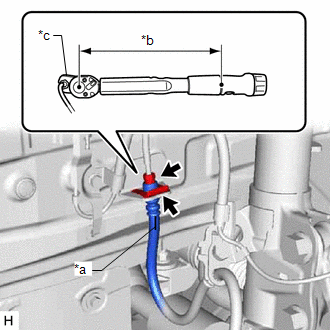
(b) Using a union nut wrench, connect the brake line to the front flexible hose while holding the front flexible hose with a wrench.
Torque:
Specified tightening torque :
15.2 N
READ NEXT:
 Components
COMPONENTS ILLUSTRATION
*1 FRONT DISC BRAKE ANTI-SQUEAL SHIM KIT
*2 FRONT DISC BRAKE PAD
*3 FRONT DISC BRAKE CYLINDER ASSEMBLY
*4 FRONT DISC BRAKE PAD WEAR INDICA
Removal
REMOVAL CAUTION / NOTICE / HINT
NOTICE:
Immediately after installing the brake pads, the braking performance may be reduced. Always perform a road test in a safe place while paying attention to
SEE MORE:
Removal
REMOVAL CAUTION / NOTICE / HINT
The necessary procedures (adjustment, calibration, initialization, or registration) that must be performed after parts are removed and installed, or replaced during engine unit removal/installation are shown below. Necessary Procedure After Parts Removed/Installed/R
Check Bus 4 Line for Short to +B
DESCRIPTION There may be a short circuit between one of the CAN bus lines and +B when there is no resistance between terminal 22 (CA2H) of the central gateway ECU (network gateway ECU) and terminal 16 (BAT) of the DLC3, or terminal 7 (CA2L) of the central gateway ECU (network gateway ECU) and termin
© 2023-2026 Copyright www.tocamry.com
