Toyota Camry (XV70): Installation
INSTALLATION
PROCEDURE
1. PRECAUTION (w/o Navigation System)
NOTICE:
- When replacing the radio and display receiver assembly, always replace it with a new one. If a radio and display receiver assembly which was installed to another vehicle is used, the following may occurs:
- A communication malfunction DTC may be stored.
- The radio and display receiver assembly may not operate normally.
NOTICE:
Click here .gif)
2. PRECAUTION (w/ Navigation System)
NOTICE:
- When replacing the radio and display receiver assembly or navigation ECU, always replace it with a new one. If a radio and display receiver assembly or navigation ECU which was installed to another vehicle is used, the following may occur:
- A communication malfunction DTC may be stored.
- The radio and display receiver assembly or navigation ECU may not operate normally.
- After replacing the radio and display receiver assembly, if "New software is not compatible with the system. Contact your dealer." is displayed on the multi-display, update the software of the navigation ECU.
NOTICE:
Click here
3. INSTALL RADIO AND DISPLAY RECEIVER ASSEMBLY
4. INSTALL NO. 1 RADIO RECEIVER BRACKET
(a) Install the No. 1 radio receiver bracket with the 2 screws.
5. INSTALL NO. 2 RADIO RECEIVER BRACKET
(a) Install the No. 2 radio receiver bracket with the 2 screws.
6. INSTALL CENTER INSTRUMENT CLUSTER FINISH UPPER PANEL ASSEMBLY (for 7 Inch Display)
(a) Engage the 3 clips to install the center instrument cluster finish upper panel assembly as shown in the illustration.
.png) |
Install in this Direction |
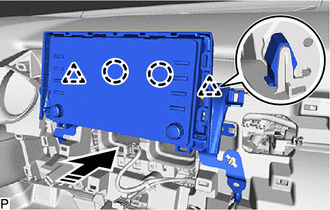
7. INSTALL RADIO AND DISPLAY RECEIVER ASSEMBLY WITH BRACKET (for 7 Inch Display)
(a) Connect each connector.
(b) Engage the 2 guides to temporarily install the radio and display receiver assembly with bracket as shown in the illustration.
|
|
Install in this Direction |
(c) Engage the 2 clips and 2 claws as shown in the illustration.
|
|
Install in this Direction |
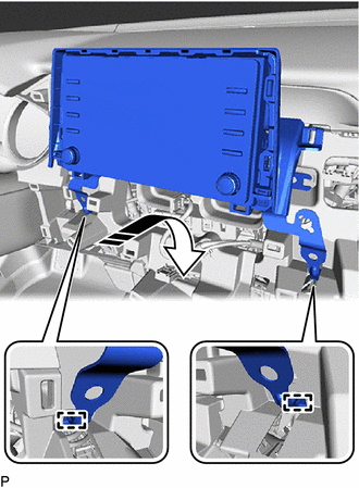
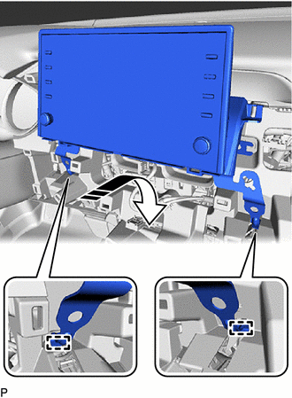
(d) Install the radio and display receiver assembly with bracket with the 4 bolts.
(e) Engage the clamp.
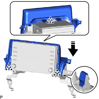
8. INSTALL RADIO AND DISPLAY RECEIVER ASSEMBLY WITH BRACKET (for 9 Inch Display)
(a) Connect each connector.
(b) Engage the 2 guides to temporarily install the radio and display receiver assembly with bracket as shown in the illustration.
|
|
Install in this Direction |
(c) Engage the 5 clips as shown in the illustration.
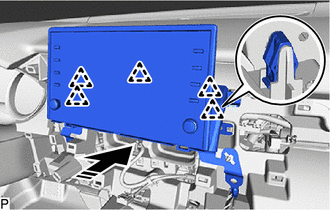
|
|
Install in this Direction |
(d) Install the radio and display receiver assembly with bracket with the 4 bolts.
(e) Engage the clamp.
9. INSTALL CENTER INSTRUMENT CLUSTER FINISH PANEL ASSEMBLY
Click here
10. INSTALL CENTER INSTRUMENT CLUSTER FINISH PANEL SUB-ASSEMBLY (for 7 Inch Display)
Click here
11. INSTALL CENTER INSTRUMENT CLUSTER FINISH PANEL SUB-ASSEMBLY (for 9 Inch Display)
Click here
12. INSTALL LOWER INSTRUMENT PANEL FINISH PANEL ASSEMBLY
Click here
13. INSTALL AIR CONDITIONING CONTROL ASSEMBLY
Click here
READ NEXT:
 Components
COMPONENTS ILLUSTRATION
*1 REAR ARMREST ASSEMBLY
*2 REAR DOOR ARMREST COVER SUB-ASSEMBLY
*3 REAR DOOR INNER GLASS WEATHERSTRIP
*4 REAR DOOR NO. 2 SERVICE HOLE COV
Removal
REMOVAL CAUTION / NOTICE / HINT
HINT:
Use the same procedure for the RH side and LH side.
The following procedure is for the LH side.
PROCEDURE 1. REMOVE REAR DOOR ARMREST COVER SUB-ASSE
SEE MORE:
Registration
REGISTRATION CAUTION / NOTICE / HINT PROCEDURE
1. VIN (VEHICLE IDENTIFICATION NUMBER) NOTICE: The Vehicle Identification Number (VIN) must be written to a replacement ECM.
HINT: The VIN is a 17-digit alphanumeric vehicle identification number. The Techstream is required to register the VIN.
(a
Intermediate Shaft Speed Sensor "A" Circuit Short to Battery (P079112,P079114,P079131)
DESCRIPTION The transmission revolution sensor (NC) detects the rotation speed of the counter gear which shows the output shaft speed of automatic transaxle assembly.
Based on the transmission revolution sensor (NC) signal and the transmission revolution sensor (NT) signal, the ECM controls engine
