Toyota Camry (XV70): Installation
INSTALLATION
PROCEDURE
1. INSTALL WATER INLET WITH THERMOSTAT SUB-ASSEMBLY
(a) Install a new gasket to the water inlet with thermostat sub-assembly.
(b) Install the water inlet with thermostat sub-assembly with the 2 bolts and 2 nuts.
Torque:
10 N·m {102 kgf·cm, 7 ft·lbf}
2. CONNECT WATER BY-PASS HOSE
(a) Connect the water by-pass hose and slide the clip to secure it.
3. INSTALL FRONT NO. 1 ENGINE MOUNTING BRACKET LH
Click here .gif)
4. CONNECT ENGINE WIRE
(a) Engage the clamp to connect the engine wire.
(b) Install the bolt.
Torque:
10 N·m {102 kgf·cm, 7 ft·lbf}
(c) Connect the water inlet with thermostat sub-assembly connector.
5. INSTALL ENGINE MOUNTING INSULATOR SUB-ASSEMBLY RH
| (a) Install the engine mounting insulator sub-assembly RH to the engine mounting spacer and vehicle body with the nut and 2 bolts. Torque: 72 N·m {734 kgf·cm, 53 ft·lbf} NOTICE: Temporarily tighten the bolt (A), and then fully tighten the 2 bolts and nut in the order of (B), (A) and (C). |
|
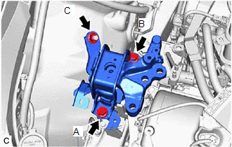
(b) Install the engine mounting insulator sub-assembly RH to the front No. 1 engine mounting bracket LH with the 3 bolts and nut.
Torque:
Bolt :
72 N·m {734 kgf·cm, 53 ft·lbf}
Nut :
42 N·m {428 kgf·cm, 31 ft·lbf}
(c) Install the suction hose sub-assembly, suction pipe sub-assembly and air conditioning tube and accessory assembly with the bolt.
Torque:
8.0 N·m {82 kgf·cm, 71 in·lbf}
(d) Engage the 2 clamps.
6. INSTALL RADIATOR RESERVE TANK ASSEMBLY
| (a) Install the radiator reserve tank assembly with the bolt and nut in the order shown in the illustration. Torque: 5.0 N·m {51 kgf·cm, 44 in·lbf} |
|
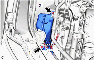
(b) Engage the clamp.
7. INSTALL ENGINE MOUNTING STAY NO.2 RH
Click here
8. INSTALL V-BANK COVER SUB-ASSEMBLY
Click here
9. ADD ENGINE COOLANT
Click here
10. INSPECT FOR COOLANT LEAK
Click here
11. INSTALL ENGINE UNDER COVER REAR RH
Click here
12. INSTALL ENGINE UNDER COVER REAR LH
Click here
13. INSTALL ENGINE UNDER COVER NO.1
Click here
14. INSTALL FRONT WHEEL OPENING EXTENSION PAD RH
Click here
15. INSTALL FRONT WHEEL OPENING EXTENSION PAD LH
Click here
READ NEXT:
 Components
COMPONENTS ILLUSTRATION
*1 ENGINE WATER PUMP ASSEMBLY
*2 NO. 2 IDLER PULLEY SUB-ASSEMBLY
*3 WATER PUMP PULLEY
*4 WATER PUMP GASKET
*5 V-RIBBED BELT
On-vehicle Inspection
ON-VEHICLE INSPECTION CAUTION / NOTICE / HINT
HINT:
Water Pump Construction Evaporation Port and Drain Plug:
*1
Evaporation Port
*2
Me
SEE MORE:
Components
COMPONENTS ILLUSTRATION
*1 ROOF CONSOLE BOX ASSEMBLY
*2 ROOF CONSOLE BOX SUB-ASSEMBLY
*3 TELEPHONE MICROPHONE ASSEMBLY
- -
Taking out the spare tire
1. Lift up the hook of the luggage
floor cover on the trunk floor.
2. Secure the luggage floor cover
using the hook provided.
3. Remove the tool tray.
2WD models
AWD models
4. Loosen the center fastener that
secures the spare tire.
When taking out or stowing the
spare tire, make
