Toyota Camry (XV70): Installation
INSTALLATION
PROCEDURE
1. INSTALL FUEL PIPE PLUG SUB-ASSEMBLY
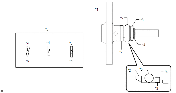
(a) Install a new O-ring, No. 1 fuel injector back-up ring, No. 2 fuel injector back-up ring and No. 3 fuel injector back-up ring to the fuel pipe plug sub-assembly as shown in the illustration.
|
*1 | Fuel Pipe Plug Sub-assembly |
*2 | No. 1 Fuel Injector Back-up Ring |
|
*3 | No. 2 Fuel Injector Back-up Ring |
*4 | No. 3 Fuel Injector Back-up Ring |
|
*5 | O-ring |
- | - |
|
*a | Opening |
*b | Overlapped |
|
*c | Stretched |
*d | Correct |
|
*e | Incorrect |
- | - |
NOTICE:
- Check that there is no foreign matter or damage on the O-ring groove of the fuel pipe plug sub-assembly.
- Check that the No. 1 fuel injector back-up ring and No. 3 fuel injector back-up ring are installed in the correct orientation.
- Make sure that the No. 1 fuel injector back-up ring, No. 2 fuel injector back-up ring, No. 3 fuel injector back-up ring and O-ring are installed in the correct order.
- Check that the opening of the No. 1 fuel injector back-up ring is not overlapped or stretched as shown in the illustration.
- After installing the O-ring, check that it is not contaminated with foreign matter and is not damaged.
(b) w/ Dust Cap:
(1) Install the dust cap sub-assembly to the fuel pipe plug sub-assembly.
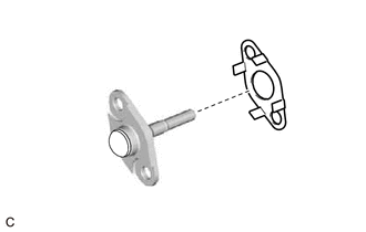
| (c) Install a new gasket to the fuel pipe plug sub-assembly as shown in the illustration. |
|
(d) Secure the fuel delivery pipe with sensor assembly LH in a vise between aluminum plates.
NOTICE:
Do not overtighten the vise.
(e) Using a 5 mm hexagon socket wrench, install the fuel pipe plug sub-assembly to the fuel delivery pipe with sensor assembly LH with the 2 bolts.
Torque:
10 N·m {102 kgf·cm, 7 ft·lbf}
(f) Remove the fuel delivery pipe with sensor assembly LH from the vise.
2. INSTALL FUEL PRESSURE SENSOR (FUEL DELIVERY PIPE WITH SENSOR ASSEMBLY LH)
HINT:
Perform "Inspection After Repair" after replacing the fuel pressure sensor (fuel delivery pipe with sensor assembly LH).
Click here .gif)
Click here
NOTICE:
- Do not remove the fuel pressure sensor from the fuel delivery pipe with sensor assembly LH.
- If the fuel pressure sensor is removed, replace the fuel pressure sensor (fuel delivery pipe with sensor assembly LH) with a new one.
3. PERFORM INITIALIZATION
(a) Perform "Inspection After Repair" after replacing the fuel pressure sensor (fuel delivery pipe with sensor assembly LH).
Click here
READ NEXT:
 Inspection
INSPECTION PROCEDURE 1. INSPECT FUEL PRESSURE SENSOR (FUEL DELIVERY PIPE WITH SENSOR ASSEMBLY LH)
NOTICE:
Do not remove the fuel pressure sensor from the fuel delivery pipe with sensor assembly
Installation
INSTALLATION PROCEDURE 1. INSTALL FUEL PIPE PLUG SUB-ASSEMBLY
(a) Install a new O-ring, No. 1 fuel injector back-up ring, No. 2 fuel injector back-up ring and No. 3 fuel injector back-up ring to the
SEE MORE:
Front Side Marker Light Bulb
ComponentsCOMPONENTS ILLUSTRATION
*1 FRONT SIDE MARKER LIGHT BULB
- - RemovalREMOVAL CAUTION / NOTICE / HINT
HINT:
Use the same procedure for the RH side and LH side.
The following procedure is for the LH side.
PROCEDURE 1. REMOVE FRONT SIDE MARKER LIGHT BULB
(
Removal
REMOVAL CAUTION / NOTICE / HINT
NOTICE:
Immediately after installing the brake pads, the braking performance may be reduced. Always perform a road test in a safe place while paying attention to the surroundings.
After replacing the front disc brake pads, always perform a road test to chec
