Toyota Camry (XV70): Installation
INSTALLATION
CAUTION / NOTICE / HINT
NOTICE:
for Type A- Always use a new bolt, tubeless tire valve and valve core when installing the tire pressure warning valve and transmitter.
- Make sure not to damage the urethane covered backside of the tire pressure warning valve and transmitter (the surface opposite to the side with the ID code) with anything sharp.
- Write down the ID number before installation.
- Check that there is no oil, water or lubricant around the rim hole and tire pressure warning valve and transmitter. Failing to do so may result in improper installation.
- Use only a specified tire valve cap. If an unspecified tire valve cap is used, it may seize to the tire pressure warning valve and transmitter.
- The tire pressure warning valve and transmitter (for type A) cannot be installed to steel wheels. Make sure to check the wheel type before installation.
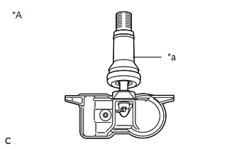
*A
for Type A
*a
Rubber Tubeless Tire Valve
- Always use a new bolt, grommet, tubeless tire valve and valve core when installing the tire pressure warning valve and transmitter.
- Check that the washer and nut are not damaged, and replace them if necessary.
- Make sure not to damage the urethane covered backside of the tire pressure warning valve and transmitter (the surface opposite to the side with the ID code) with anything sharp.
- Write down the ID number before installation.
- Check that there is no oil, water or lubricant around the rim hole, tire pressure warning valve and transmitter, washer and nut. Failing to do so may result in improper installation.
- Use only a specified tire valve cap. If an unspecified tire valve cap is used, it may seize to the tire pressure warning valve and transmitter.
PROCEDURE
1. INSTALL TIRE PRESSURE WARNING VALVE AND TRANSMITTER (for Type A)
(a) Using a T10 "TORX" socket wrench, install the tire pressure monitor sensor to the new tubeless tire valve with a new bolt.
Torque:
1.2 N
READ NEXT:
 Disposal
DISPOSAL CAUTION / NOTICE / HINT
HINT: The tire pressure warning valve and transmitter is powered by a lithium battery. When disposing of the tire pressure warning valve and transmitter, remove the
SEE MORE:
Left Rear Wheel Speed Sensor Circuit Voltage Out of Range (C050C1C)
DESCRIPTION Refer to DTC C050C12 Click here
DTC No. Detection Item
DTC Detection Condition Trouble Area
C050C1C Left Rear Wheel Speed Sensor Circuit Voltage Out of Range
When the vehicle is being driven in a straight line at a speed of 20 km/h (12 mph) or more
Diagnosis System
DIAGNOSIS SYSTEM DESCRIPTION (a) Blind spot monitor data and Diagnostic Trouble Codes (DTCs) can be read from the Data Link Connector 3 (DLC3) of the vehicle. When the system seems to be malfunctioning, use the Techstream to check for malfunctions and perform repairs.
CHECK DLC3 (a) Check the DLC3
© 2023-2026 Copyright www.tocamry.com
