Toyota Camry (XV70): Installation
INSTALLATION
CAUTION / NOTICE / HINT
HINT:
- Use the same procedure for the RH side and LH side.
- The following procedure is for the LH side.
PROCEDURE
1. INSTALL FRONT DOOR UPPER WINDOW FRAME MOULDING
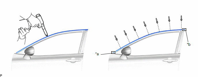
(a) Engage the guide and clamp to temporarily install the front door upper window frame moulding to the door frame.
|
*a | Clamp |
*b | Guide |
(b) Using an air riveter or hand riveter with a nose piece, install the front door upper window frame moulding with 7 new rivets.
HINT:
If the mandrel of the rivet does not come off on the first operation of the rivet gun, slide the rivet gun forward on the mandrel and operate it again.
NOTICE:
- Do not pry the rivet with the riveter, as this will cause damage to the riveter and mandrel.
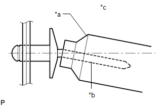
*a
Riveter
*b
Mandrel
*c
Incorrect
- Confirm that the rivets are seated properly against the moulding.
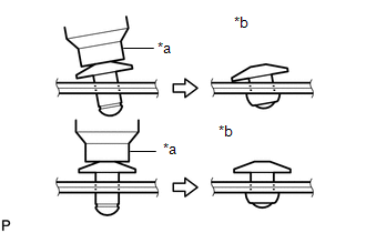
*a
Riveter
*b
Incorrect
- Do not tilt the riveter when installing the rivet to the moulding.
- Do not leave any space between the rivet head and moulding.
- Do not leave any space between the moulding and door frame. Firmly hold the 2 items together while installing the rivet.
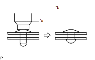
*a
Riveter
*b
Incorrect
2. INSTALL FRONT DOOR REAR WINDOW FRAME MOULDING
HINT:
When installing a new front door rear window frame moulding, heat the vehicle body and front door rear window frame moulding using a heat light.
Heating Temperature|
Item | Temperature |
|---|---|
|
Vehicle Body | 40 to 60 |
READ NEXT:
 Front Pillar Upper Cover
ComponentsCOMPONENTS ILLUSTRATION
*1 FRONT DOOR FRONT LOWER FRAME UPPER COVER
- - RemovalREMOVAL CAUTION / NOTICE / HINT
The necessary procedures (adjustment, calibration
Components
COMPONENTS ILLUSTRATION
*1 LUGGAGE COMPARTMENT DOOR OUTSIDE GARNISH PROTECTOR
*2 LUGGAGE COMPARTMENT DOOR OUTSIDE GARNISH SUB-ASSEMBLY
*3 NO. 2 LUGGAGE COMPARTMENT D
SEE MORE:
Inspection
INSPECTION PROCEDURE 1. INSPECT KNOCK CONTROL SENSOR
(a) Measure the resistance according to the value(s) in the table below.
Standard Resistance:
Tester Connection Condition
Specified Condition
1 - 2 25°C (77°F)
120 to 280 kΩ If the result is not
Removal
REMOVAL CAUTION / NOTICE / HINT
HINT:
Use the same procedure for the RH side and LH side.
The following procedure is for the LH side.
PROCEDURE 1. REMOVE SPARE WHEEL COVER ASSEMBLY
Click here 2. REMOVE SPARE WHEEL COVER TRAY
Click here 3. REMOVE NO. 1 LUGGAGE COMPARTMENT
